Table of contents
Noll
14th pictures
Noll
1/14
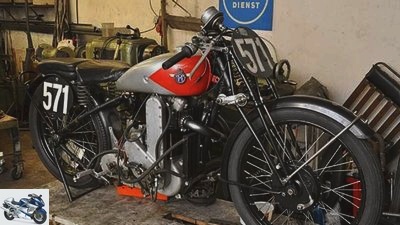
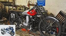
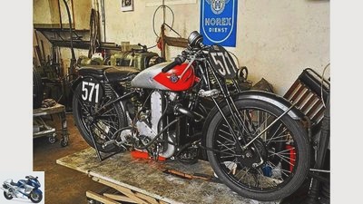
The restoration of the successful Horex team from 1935. The racing machine gets a general overhaul.
Noll
2/14
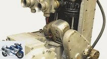
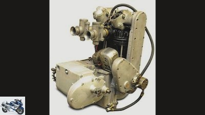
The two-cylinder racing engine based on the Horex 800 twin received a makeover as part of the restoration of the Braun / Badsching team.
Noll
3/14
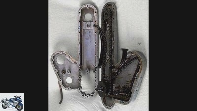
The timing chain and the chain that drives the ignition magnet in the racing engine run in the box on the right-hand side of the engine.
Noll
4/14
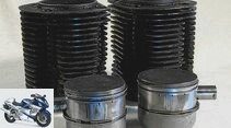
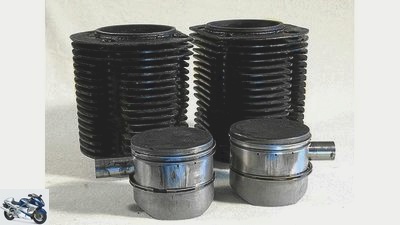
The individual cast iron cylinders are ribbed more strongly than the series parts.
Noll
5/14
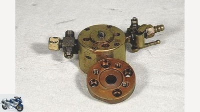
An external, subsequently installed oil pump ensures the lubrication of the two-cylinder racing engine.
Noll
6/14
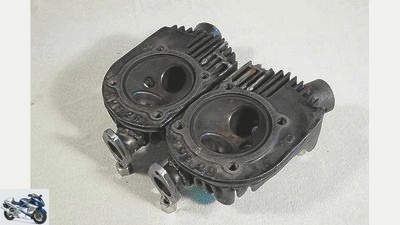
The individual cylinder heads made of gray cast iron come from the second series of the Horex Twin.
Noll
7/14
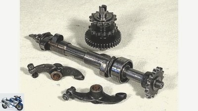
The chain-driven, overhead camshaft was an unusual solution in its time.
Noll
8/14
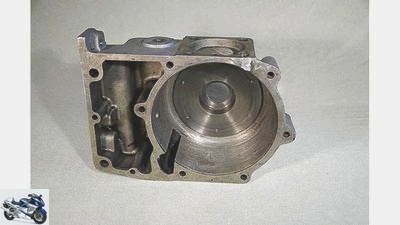
The vertically divided crankcase accommodates a bearing plate for the third crankshaft bearing in the middle. The timing chain sprocket sits on the right-hand side
Noll
9/14
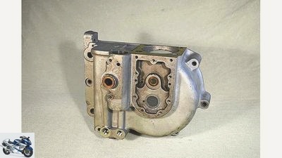
The vertically divided crankcase accommodates a bearing plate for the third crankshaft bearing in the middle. The timing chain sprocket sits on the right-hand side.
Noll
10/14
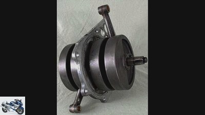
In the series, the bearing shield was made of aluminum.
Noll
11/14
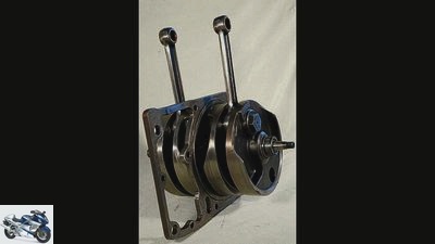
In the racing engine with the crankshaft made from NSU parts, the bearing shield was made of steel.
Noll
12/14
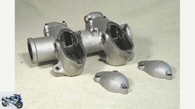
The timing case accommodated the camshaft and rocker arm. The covers can be removed to adjust the valve clearance.
Noll
13/14
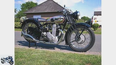
The Horex S 800 was a thoroughbred sports motorcycle of the very highest quality.
Noll
14/14
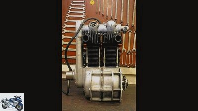
The narrow parallel twin shone with an ultra-modern concept.
counselor
workshop
Restoration of the Horex team
Restoration of the Horex team
The 1935 Horex racing machine is being restored
Content of
A racing machine usually experiences constant further development right from the start. Like the Horex team from 1935, which even in the 1950s was still fighting for a place and victory in competitions.
Jurgen Noell
13/01/2012
Engines with two cylinders were not necessarily considered revolutionary in motorcycle construction in Germany in the 1920s and 30s. Even before the First World War, companies such as NSU or Wanderer relied on the two-cylinder, and in 1923 BMW fitted its first model with a boxer engine. Two-cylinder engines were also very popular in England. Companies like Jap or AJS created their reputation with it at the beginning of the 1920s.
In the United States, two-cylinder engines were even considered the standard engine at Indian and Harley-Davidson. Those who could afford the luxury bought a model with a four-cylinder in-line engine. But with a few exceptions, most two-cylinder had a V-shaped or boxer layout.
Parallel two-cylinder engines were far less common. But it was precisely in this construction principle that Horex designer Hermann Reeb saw great potential for high-displacement four-stroke engines. Reeb’s first drafts date back to 1931. The design and construction of the first prototype engine took place in silence. According to Horex director Fritz Kleemann, Hermann Reeb is said to have put the parallel twin up and running on the test bench for the first time on Christmas Eve 1932. The construction was bursting with new, revolutionary ideas. The engine with a 360 degree crank pin offset, i.e. pistons running in the same direction, was planned with a 90 millimeter stroke and 65 millimeter bore as a 600 and with a 75 millimeter bore as an 800 sports engine.
With 30 HP at 5000 rpm and the tame compression ratio of 6: 1, the 800 still had plenty of thermal and mechanical reserves. The individually cast cylinders and cylinder heads were made of gray cast iron and were screwed to the light metal crankcase with four long tie rods each. This arrangement allowed good cooling. Integrated into the crankcase, behind the cylinders was the 2.25 liter oil tank that housed the engine oil for the dry sump lubrication. This eliminates the need for a separate oil tank.
Concerns that the engine oil could become too hot due to the lack of airflow cooling due to constant use in the crankcase turned out to be unfounded. In a report by “Das MOTORRAD” in July 1940 about the “Development of a Fast Apparatus”, the oil temperature never exceeded 60 degrees Celsius in any operating condition. However, the oil supply to the camshaft running in two ball bearings stopped completely after a short period of operation. A circumstance that had already cost the previous owner of the machine two new camshafts. The cause was a ball valve in the riser pipe to the camshaft housing, the ball of which tended to jam if the oil was even slightly contaminated, thus blocking the pipe.
Other oil supply lines, even the oil pump that is usually flanged to the outside of the engine in other models, were located in the engine and contributed to the tidy overall appearance. A triple-bearing and dismountable crankshaft drove the timing chain housed in an aluminum shaft on the right-hand side. A second roller chain was used to drive the oil pump and the alternator mounted behind the cylinder.
The encapsulation of the valve stems and valve springs was considered to be extremely progressive. Inadequate lubrication of valves and guides, as well as the abrasive effect of road dust, led other manufacturers to heavy wear. For the first time came to one Horex Instead of the previously common spark plugs with M 18 x 1.5 thread, space-saving plugs with M 14 x 1.25 thread are used. Two Amal carburettors prepared the mixture.
There were structural differences between the early and later series models: for example, the enlargement of the cooling fins over the exhaust ports of the cylinder head. The initially cylindrical ribbing of the cast cylinder also tapered downwards later. A second tensioning rail improved the guidance of the roller chain to the overhead camshaft. The connecting lines of the rocker arm housing for the oil return, which were initially cast together with the housings, tended to break. Finally, elastic copper cables provided a remedy.
The engines of the first series also lacked an oil dipstick, so that checking was only possible visually and by removing the oil tank vent. You could only refill yourself through the vent. Later there was a dipstick and thus an easily accessible place for refilling. The later introduced adjusting screw, with which the oil supply to the crankshaft and the camshaft housing could be regulated, did not have the engines of the first series either. The eight tie rods that clamped the cylinders and cylinder heads onto the crankcase initially had M 8 x 1 threads, later M 10 x 1. In addition, the designers improved the return to the oil tank. The potential of this design was clearly demonstrated in 1935 at the German championship in the team class, which the Karlsruhe Braun / Badsching team won.
Noll
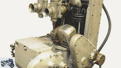
The two-cylinder racing engine based on the Horex 800 twin received a makeover as part of the restoration of the Braun / Badsching team.
During the restoration, the engine revealed other interesting details. Already visible from the outside, the two cylinders are not Horex standard parts. As with the commercially available S6 and S8 models, they are made of gray cast iron, but differ in the number and shape of the cooling fins from the series. 17 versus 13 ribs should take the higher thermal load into account in the racing engine.
The retrofitted, external oil pump with its various lines is even more noticeable on the right-hand side. A gear pump with a high delivery capacity replaced the piston pump integrated in the series in the motor housing, which worked with a significantly lower delivery volume. In addition, the racing machine was given a voluminous, external oil tank with an oil cooler.
The cylinder heads are from the second series, which are characterized by larger ribbing, especially in the area of the exhaust valves, and in which the intake ports are subsequently machined. Various work was required before they could be reused, during which time numerous broken cooling fins had to be replaced. The inlet and outlet valves have disc diameters of 40 and 38 millimeters, respectively. The shafts of the inlet and outlet valves measure nine millimeters.
The dismantling of the motor housing finally revealed some very interesting things. Instead of a Horex crankshaft, a special shaft emerged, the origin of which was initially a mystery. But thanks to small embossments on the shafts of the two connecting rods, an NSU specialist identified the good piece as a construction based on two single-cylinder racing shafts from the legendary NSU vertical shaft engines from the years before the Second World War. Both crankshafts are pressed together and triple bearings. In contrast to the series engine, in which an aluminum bearing plate takes up the center bearing, the counterpart of the racing engine is made of steel and is significantly more torsion-resistant.
The dimensions for bore and stroke of 81 x 99 millimeters result in a displacement of 1019 cm³. Presumably, the holes originally had a diameter of 80 millimeters, corresponding to a displacement of 955 cm³, and were repeatedly drilled out through repeated repairs. The reason for the relatively low compression of almost 1: 7 can be traced back to the compressor operation, which required a lower compression. On the right-hand side, the crankshaft runs in a roller bearing, while on the left-hand side it runs in a simple deep groove ball bearing. The reason for this arrangement is not entirely understandable, as one would rather equip the more heavily loaded output side to the primary drive with a roller bearing, as these can absorb significantly higher radial forces due to their design.
Whether the large steel plate in the right motor housing was installed as the seat of the ball bearing to better absorb the bearing forces or whether it should only replace a worn bearing seat as part of regular repairs will also remain a secret of the designers.
In order to improve the lubrication, the oil circuit was obviously rebuilt as early as the 1930s. Historical photos show that the racing team already had a separate oil tank back then and that the oil reservoir in the crankcase of the series version was not used. The crankcase, which is neither marked with an engine number nor any other markings, was not even machined at the point where the pump normally sits, so a series part has never been installed here.
With the installation of the separate oil tank and the gear oil pump, the lubrication system also changed. Two of the lines are used for the flow and return to and from the oil tank. The pump sucks in the oil from the crankcase via a third. Further connections supply the left and right connecting rod bearings as well as the overhead camshaft.
The highly interesting engine design demonstrated its performance and reliability at the end of the 1935 season with the German motorcycle championship for sideboards up to 1000 cm³ and will soon revive the newly resurrected tricycle.
Related articles
-
Restoration of the BMW R 80 G-S, part 1 engine
Cook 21 pictures Cook 1/21 The good news first: It’s working. Velvety soft, with an impeccable chassis and really amazing qualities. A classic for every…
-
Team Suzuki Classic Katana: Extremely sharp long sword
Team Suzuki Classic 24 pictures Team Suzuki Classic 1/24 The Suzuki Classic team is behind the racing activities of Suzuki in historic motorsport. Team…
-
Visit to the Horex factory in Augsburg
Artist 23 pictures Horex 1/23 Horex 6-cylinder motorcycle: working on the model of the cylinder head. Horex 2/23 Horex 6-cylinder motorcycle: the red…
-
Aprilia MotoGP Team 2021: Aleix Espargaró and Lorenzo Savadori
Aprilia 15th pictures Aprilia 1/15 The Aprilia Racing Team Gresini presents its team for the MotoGP season 2021 shortly before the first test drives in…
-
Restoration of the BMW R 80 G-S part 4 engine and carburetor adjustment
Cook 23 pictures Cook 1/23 Small and big changes make the almost 70 hp of the renovated R 80 G / S. Cook 2/23 The new, original air filter sits on this…
-
Interview HRC Team Principal Dakar Rally
HRC 30th pictures Speedbrain 1/30 After the first three stages, Joan Barreda Bort already has two victories on the account and lets the Honda works team…
-
Laverda specialists Orange Cycle Team
Siemer 24 pictures Siemer 1/24 Siemer 2/24 Siemer 3/24 Siemer 4/24 Siemer 5/24 Siemer 6/24 Siemer 7/24 Siemer 8/24 Siemer 9/24 Siemer 10/24 Siemer 11/24…
-
Restoration Sauerborn-Munch TTS 1200 Turbo
Siemer 24 pictures Siemer 1/24 The Munch was owned by Arno Sauerborn for 44 years. In doing so, it often had to serve as a motorhome: in the very first…
-
Tech Team’s Monkey Garage workshop
Blacksmith 26 pictures Blacksmith 1/26 Blacksmith 2/26 … almost to the handbag. Blacksmith 3/26 With the handlebars down, it mutates .. Blacksmith 4/26…
-
What moved the MOTORRAD editorial team in 111 years
archive Sports & scene What moved the MOTORRAD editorial team in 111 years What moved the MOTORRAD editorial team in 111 years You know what …? There…