Table of contents
- PS technology series part 4 Crankshaft drive / crankshaft
- Mass moments and balance shafts
- Torque peaks and pumping losses
- Manufacture and balance crank shafts
- Big Bang: Protect tires, control drifts
archive

11 pictures
Yamaha
1/11
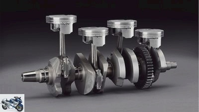
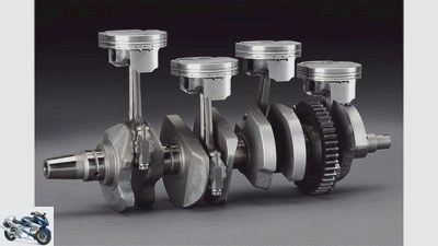
Only the crankshaft converts the combustion pressure acting on the pistons into rotation via the connecting rod. A process that mobilizes enormous forces. But not all are welcome.
Cook
2/11
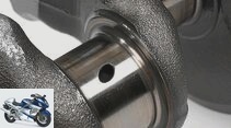
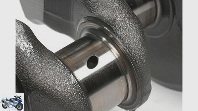
Crank pin with oil hole and noticeably large radii at the transition to the cam disc. This prevents what is known as a notch effect, which could lead to breakage of the shaft due to the high bending and torsional forces. The surface is hardened and then sanded.
Cook
3/11
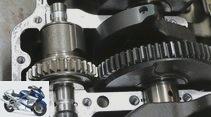
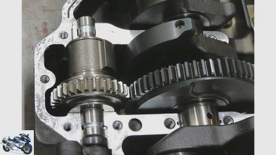
In-line four-cylinder engine of the Kawasaki Z 1000 with a
small balance shaft rotating in front of the crankcase. This rotates in the opposite direction at twice the crankshaft speed, reducing the second-order inertia forces and thus the high-frequency vibrations.
Cook
4/11
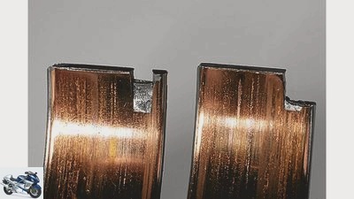
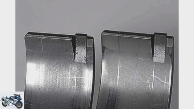
… this relatively soft layer rubs off down to the copper layer. The motor announces such bearing damage with a pounding running noise under load and heavy vibrations.
Cook
5/11
Bearing shells consist of a steel core, a wafer-thin copper alloy and the matt gray lead / tin / copper bearing material. In the event of a lack of oil or dilution …
6/11
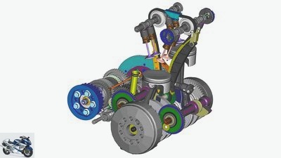
180-degree two-cylinder in-line engine: The mass balance is achieved with a balance shaft running in front of and behind the crankcase with large counterweights.
7/11
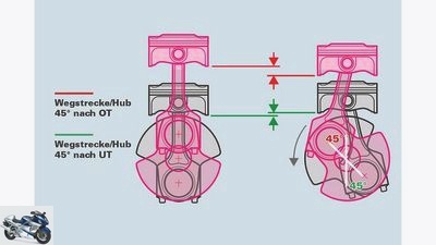
Second-order inertia forces arise from the fact that the pistons accelerate faster at the top dead center than at the bottom reversal point, which means that different inertia forces build up. The reason: The deflection angle of the connecting rod influences the distance covered by the piston. The longer the connecting rod, the smaller the deviations.
8/11
On the left the boxer: Although the pistons run parallel, lift
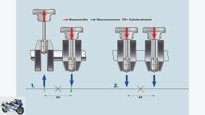
the mass forces are completely on. In addition, there are no second-order inertia forces, since both pistons reverse at the top and bottom dead center at the same time, i.e. have identical acceleration curves. What remains are the tilting movements of the mass moments, which, however, are small due to the small distance between the cylinders – the BMW boxer engine does not have a crankshaft center bearing. Important for the boxer: precisely balanced pistons and connecting rods as well as a neatly balanced crankshaft.
Right the in-line four-cylinder: With a stroke offset of 180 degrees each, the in-line four has an almost perfect mass balance. The moments of inertia also cancel out because all four cylinders work in one plane and no tilting moment arises. The high-frequency, annoying four-cylinder vibrations that often destroy headlight bulbs, license plates and mirror glasses are the result of second-order inertia forces and have to be fought using a balance shaft that rotates at twice the engine speed.
9/11
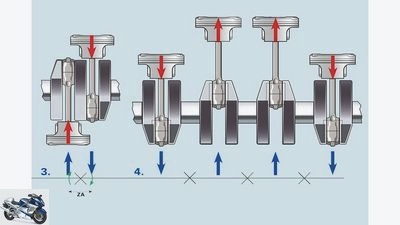
On the left is the 180 ° in-line two-cylinder: due to the reciprocal movement of the pistons, the inertial forces of the piston and connecting rod cancel each other out. Due to the relatively large cylinder distance (ZA), however, the masses alternately generate a tilting moment (green arrows) around the central axis. In order to keep the vibrations away from the driver, such engine designs work with balance shaft (s) and / or elastic mountings in the frame.
On the right the parallel two-cylinder: the classic synchronous rotor generates enormous vibrations by doubling the oscillating masses, which can only be effectively combated with balancer shafts or a swiveling connecting rod (BMW F 800 engines). However, there are no mass moments in the parallel twin. The old English engine construction (Norton Commando, etc.) dispensed with the balancer shafts and instead decoupled the entire engine including the swing arm by means of massive rubber bearings in the so-called “Isolastic frame”.
Yamaha
10/11
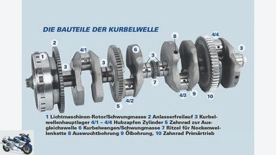
Are you kidding me? Are you serious when you say that, “it just turns”: a modern crankshaft takes on a lot of important secondary activities.
Cook
11/11
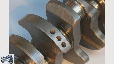
The counterweights of the crankshaft are oversized and he-
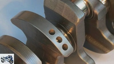
possible that, if necessary, an exact balancing is produced by means of compensating bores. When tuning for racing purposes, these counterweights are often drastically reduced in order to reduce the total flywheel mass.
counselor
technology & future
crankshaft
PS technology series part 4
Crankshaft drive / crankshaft
Content of
The pistons move up and down in the cylinders. Connecting rods transmit this linear movement to the rotating crankshaft. This creates tremendous forces and moments – but not all of them are welcome.
Werner Koch
07/16/2013
When the pistons hammer the crankshaft with all the energy contained in the expensive fuel, inertial forces and moments of inertia are created. Without taming, they would dismantle a motorcycle into its individual parts within a few kilometers.
Buy complete article
PS technology series part 4
Crankshaft drive / crankshaft
6 pages) as PDF
€ 2.00
Buy now
As in the last part of the PS-Technik series in issue 7/2013 described, a piston of a BMW S 1000 RR alone develops a force of over 6000 Newtons at 12,000 rpm, which corresponds to a mass of around 600 kilograms – twice with each rotation, namely when the piston is at the top and bottom Dead center is braked from around 130 km / h to zero and then fully accelerated again, i.e. 400 times per second.
The problem with this highly dynamic process: The inertial forces and moments of inertia of the crank drive are passed into the overall engine system – and from there into the chassis – and, depending on the number of cylinders and configuration, generate more or less strong vibrations. Even if counterweights on the crankshaft can balance some forces and moments, there are still considerable residual vibrations, for which some modern engines use balance shafts.
Two-cylinder in-line engines with a 180 degree crank pin offset do have a good mass balance, but the designers of such engines struggle with the moments of inertia. These are caused by the design-related cylinder spacing at which the two opposing pistons act as a lever arm and want to tilt the engine around its longitudinal axis.
workshop
PS technology special
Further training for motorcyclists
read more
Mass moments and balance shafts
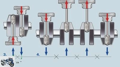
The low crank pin misalignment on the BMW Boxer (left) reduces free mass moments immensely.
Due to the lower crank pin misalignment, boxer engines with free moments of inertia have fewer problems. In four-cylinder engines with the usual crank pin offset of 180 degrees, the first-order inertial forces and the moments of inertia are completely canceled out by the opposing pistons and connecting rods.
This is not the case with the engine of the Yamaha YZF-R1 with asymmetrical crank pin offset and corresponding ignition intervals. A balance shaft is essential for smooth running. The fine, nasty vibrations are distributed over the entire chassis.
What remains with single-cylinder and two-, three- and four-cylinder in-line engines are free inertia forces of the second order. The cause lies in the geometry of the crank drive, in which the piston moving upwards has a different acceleration than its counterpart moving downwards from TDC at the same time. This changes the resulting dynamic inertia force, and this can only be combated by a balancer shaft that rotates at twice the crankshaft speed, as is the case with the Kawasaki Z 1000 engine, for example.
Large centrifugal masses in the form of massive crank webs or heavy alternator rotors also help to make the engine run smoothly and smoothly, especially at low speeds. However, large crankshaft centrifugal masses make the machines less manageable: the high gyroscopic forces such motors require more steering force when changing lean angles or when turning and folding in a flash.
However, when determining the centrifugal masses, the power development on the rear wheel must also be taken into account: Too little centrifugal mass promotes punching when braking, can trigger chattering, i.e. high-frequency vibrations on the front wheel, and excessively stress the rubber on the rear tire due to aggressive torque peaks.
Therefore, a compromise is important here in order to combine maximum handiness with smooth power delivery. Racing engineers therefore like to use variable centrifugal masses in the form of alternator rotors of different weights or screwed additional weights.
Torque peaks and pumping losses
Engine vibrations arise exclusively from inertia forces and moments of inertia, but not from combustion, i.e. the gas force that pushes the piston down. Since the gas forces, starting from the spark plug’s flash point, spread evenly in all directions and levels, they cancel each other out.
However, when accelerating, the non-uniform torque of the engine acting on the clutch, transmission, secondary drive and rear wheel generates torsional vibrations. The perceptible vibrations are the result of the torque peaks, which can trigger loud chain whipping or hard mechanical beating in the drive train, especially in single and two-cylinder engines.
The wild up and down of the pistons, depending on the offset of the crank pins, causes so-called pumping losses, which arise because the pistons racing downwards displace and compress air.
If a crankshaft offset by 180 degrees with free openings from one cylinder to the other creates the perfect volume balance, the pistons of parallel twins or V-engines with narrow cylinder angles force the air together. And that costs performance and requires sophisticated engine ventilation.
Or, like KTM, the air / oil mixture can be sucked out of the sealed crankcase using a pump. This creates negative pressure, which drastically reduces pumping losses and increases engine performance despite the additional oil pump.
Manufacture and balance crank shafts
Cook
When balancing crankshafts, the oversized crank webs are made easier by compensating bores.
To withstand the forces and bending moments, modern crankshafts are drop forged from high-strength steel. When machining the ground plain bearing surfaces for the main and connecting rod bearings, generous radii ensure that the shaft does not have any predetermined breaking points that would lead to a major break due to the enormous torsion and deflection.
For permanent storage, current crankshafts mainly rotate in plain bearings that are supplied with an oil pressure of two to five bar directly from the oil pump. The plain bearing shells usually consist of two bearing materials that are sprayed onto the split steel half-shells. Up until the 1980s, many Japanese engines were equipped with crankshafts with roller bearings.
These so-called “built shafts” were pressed from individual parts and rotated in roller bearings and at least one ball bearing that took over the axial guidance. Advantages: low friction, insensitive to lack of lubricant. Disadvantages: enormously high manufacturing costs, rough engine running due to increased bearing play.
Crankshafts, regardless of the number of cylinders, must be balanced to ensure that they run smoothly. This process is carried out by special dynamic machines that display any desired balancing factor. In order to be able to carry out the desired balancing on the crank webs, the centrifugal masses attached opposite the crank pin are facilitated by holes if necessary. Special companies can balance crankshafts with an accuracy of half a gram and thus create the best conditions for smooth running.
In addition to the stroke, the crankshaft design also determines the ignition offset of the individual cylinders to one another, keyword “big bang”. In V engines, in contrast to in-line engines, the cylinder spread causes an asymmetrical ignition offset. Exceptions are the in-line engines from Yamaha YZF-R1 and M1-MotoGP. In the case of two-cylinder engines, synchronous rotors have a symmetrical, counter rotors an asymmetrical ignition offset.
Special features are the BMW F 800 and Yamaha TRX 850 engines modified for Husqvarna. The two in-line engines with asymmetrical ignition offset simulate the sound and torque output of a V-engine.
Big Bang: Protect tires, control drifts
And what should all the effort be for? Just to give the Yamaha M1 from Jorge Lorenzo and Valentino Rossi a great sound, the backward rotating crankshaft was certainly not redesigned into a big bang. Especially since this construction principle requires a balancer shaft and the exhaust gas flows cannot be used as efficiently as with a symmetrical in-line engine. So the whole principle also eats up performance.
To understand what happens when you accelerate out of corners, you have to look at the power output in detail. Because the tire is not constantly subjected to the full engine torque. The torque pulsates between the individual work strokes, i.e. two per crankshaft revolution in the four-stroke four-cylinder.
The idea behind the big bang engine is to place two work cycles, i.e. two torque peaks as closely as possible one behind the other, which briefly put more stress on the tire and cause increased slip. However, this is followed by a correspondingly longer recovery phase in which the tire does not have to transfer any circumferential forces, i.e. it is thermally and mechanically relieved.
With this trick one tries on the one hand to protect the tire and on the other hand to make the drift easier for the driver to control. Electronic traction control also has it easier with the big bang principle, since the time intervals of one “Double ignition” to the next are larger than for motors with a 180 degree crank pin offset.
Does the electronics receive the signal “Too much slip”, there is more time to reduce the tire spinning with a cylinder-selective ignition switch-off. In series production, the Yamaha R1 engine and the Aprilia V4 engines work according to the big bang principle.
Related articles
-
Yamaha 7th pictures Yamaha 1/7 In PS 7/2015, reader Gerrit Hawich asked about the function and background of the Yamaha R1 engine with crossplane…
-
fact 16 pictures archive 1/16 The primary drive and clutch shovel the mountains of torque from the crankshaft to the gearbox. A task that can only be…
-
BMW F 800 R and Husqvarna Nuda 900 – the technology behind it
Gargolov counselor technology & future BMW F 800 R and Husqvarna Nuda 900 – the technology behind it BMW F 800 R and Husqvarna Nuda 900 in a technology…
-
Bilski motorcycles Torque and speed Torque and speed Minimax Worlds collide when a sports engine is supposed to tease out top performance from a minimal…
-
Cylinder piston connecting rod
fact 15th pictures 1/15 The conventional connecting rod, on the other hand, is machined in several steps and fixed with a fit. The two connecting rod…
-
Endurance test final balance BMW F 800 S
mps photo studio motorcycles Endurance test final balance BMW F 800 S Endurance test final balance BMW F 800 S They kissed and they hit her Andreas Bildl…
-
Jahn motorcycles Master Crosss 2004 Master Crosss 2004 High-flyer wanted Eight journalists from the most important magazines in Europe are testing 24…
-
MV Agusta F3 engine: the technology
manufacturer counselor technology & future MV Agusta F3 engine: the technology Technology: MV Agusta F3 engine The engine of the super sports car from MV…
-
BMW motorcycle 6th pictures BMW motorcycle 1/6 In the F 750 GS there are tamer 77 HP (57 kW) at 7,500 rpm and 83 Nm maximum torque at 6,000 rpm. BMW…
-
Gleanings from the Eicma fair in Milan
Motorcycle fair in Milan EICMA 2021 Presented by counselor technology & future Gleanings from the Eicma fair in Milan Gleanings from the Eicma fair in…