Table of contents
- PS-Technik series part 16 Motorcycle electrical system and wiring diagram
- Circuit is literally short-circuited
- Hard to see through, underarm-thick cable harnesses
- Troubleshooting tips
Cook

15th pictures
Cook
1/15
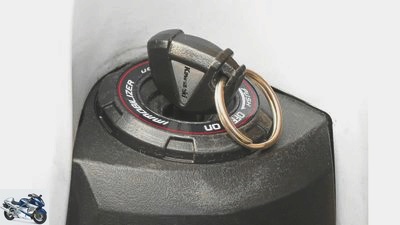
Insert the key, turn it, press the button and off you go. What is now a matter of seconds and a piece of cake even without technical expertise, was a real procedure that drove many motorcyclists to despair in the 1970s.

Cook
2/15
The wire diameter should be notched from around one millimeter in the upper arch with silk cutters or pincers to half the wire thickness so that the melting point starts at this point in good time before the cable burns.
Cook
3/15
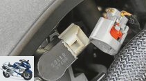
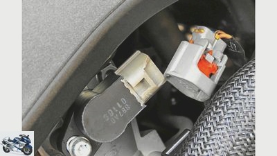
In our example, the plug contact of the throttle valve sensor slipped off because the safety clip was torn off.
Cook
4/15
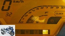
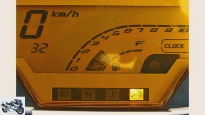
If you press and hold the reset button, the number assigned to the faulty component lights up instead of the odometer, in our case 32. With this method, the fault can be identified quickly. Whether it can be fixed quickly depends on whether the sensor is defective or just the plug contact is poorly connected.
Cook
5/15
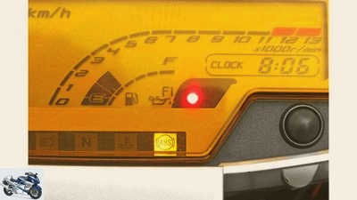
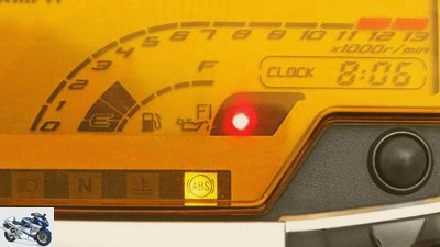
The engine accelerates with a delay, jerks and is very difficult to drive. At the same time, the red warning lamp and the FI signal flash in the cockpit.
Cook
6/15
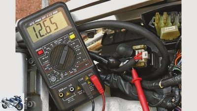
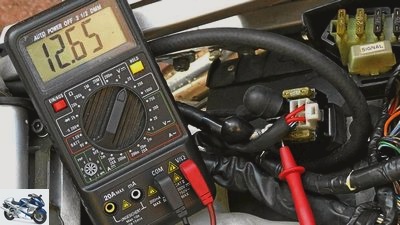
A volmeter tester is essential for some electrical faults. The test lamp can only be used to determine whether the cable is live, but no voltage is displayed.
Cook
7/15
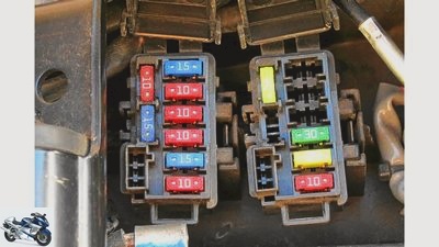
… which are clearly identified by the color and always
should be available as a replacement.
Cook
8/15
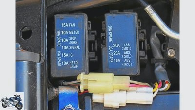
Fuse box with printed assignment of the respective consumer and the amperage of the fuses…
Cook
9/15
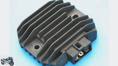
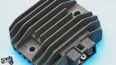
The voltage regulator and rectifier are located in an aluminum housing with cooling fins.
Cook
10/15
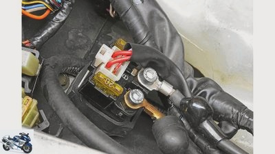
Starter relay where the positive cables of the battery (B) and the starter motor (M) converge and the on-board network is supplied with power.
Cook
11/15
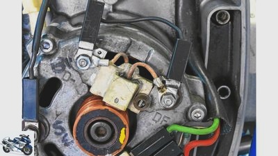
Field-regulated alternator in which an excitation current from the battery acts on the electromagnet. Two “coals” transmit the current to the brass running surfaces of the rotor, which have to be replaced regularly as wearing parts.
Cook
12/15
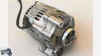
Piggyback alternator, which sits protected from falling behind the cylinder block and is driven via an intermediate shaft.
Cook
13/15
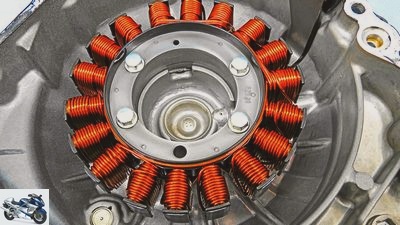
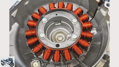
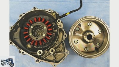
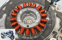
Maintenance-free alternator stator with star-shaped windings (left) and the rotor with embedded north and south pole magnets.
Cook
14/15
Only when the immobilizer is deactivated by the transmitter in the knob of the ignition key does the electronics release all signals for the engine control, the engine can then be started.
Cook
15/15
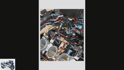
View under the tank of a Kawasaki Z 1000:
1. Servomotor of the secondary throttle valve
2. Vacuum sensors for the suction pipes
3. Ignition signal for the spark plug connector / ignition coils
4. Control valve for the secondary air supply
5. Secondary air supply to the outlet ducts
6. Plug contact to the amplifier of the immobilizer
7. Main wiring harness to consumers
counselor
workshop
Electrical wiring diagram
PS-Technik series part 16
Motorcycle electrical system and wiring diagram
Content of
Volts, watts, ohms – without us there is no electricity. How and from where the electric currents flow in the motorcycle, without which nothing would turn – here it is:
Werner Koch
09/16/2014
Insert the key, turn it, press the button and off you go. What is now a matter of seconds and a piece of cake even without technical expertise, was a real procedure that drove many motorcyclists to despair in the 1970s. At that time, fuel and air had to be carefully dosed with a kick starter, choke lever and the right turn of the throttle grip, today countless sensors and lightning-fast computers arrange the perfect start behavior and flawless concentricity from the first turn. Before the key disappears into the lock, a signal in the knob of the electronic immobilizer key gives the OK. Only then does the ignition box enable all signals for the start. If this signal is missing, a warning light symbolized as a key usually flashes in the display. The engine spins, but neither injection nor ignition are activated, and the engine does not start. Only when the transmitter is recognized does the electronic ignition box provide a set-up based on innumerable information from the engine sensors, with which the engine starts working at the first spark under all weather and temperature conditions.
Buy complete article
PS-Technik series part 16
Motorcycle electrical system and wiring diagram
6 pages) as PDF
€ 2.00
Buy now
To ensure that all units in the vicinity of the engine are supplied with sufficient voltage, a relay cuts the permanently switched low beam and other consumers as soon as the starter motor is supplied with power. After all, the electric drive eats up a lot of electricity and could cause starting difficulties if the basic voltage of the battery weakens. Because at the same time as the starter, injection nozzles, ignition coils, the servomotors on the throttle valves and all other “vital” consumers must be supplied with electricity. And only the battery can provide this at the moment of starting, since the alternator does not yet generate any usable electrical power at the low engine speed. Only after around 1000 revolutions, i.e. when the motor is working independently, do the magnetic fields around the coils build up such a high voltage that the charge control, if present, goes out and the excess energy can flow to the battery as charging current.

workshop
PS technology special
Further training for motorcyclists
read more
Circuit is literally short-circuited
The alternator output is designed for modern, fully equipped machines at around 600 watts. The generator set is usually located directly on the engine’s crankshaft stub and runs in the cooling oil mist of the engine lubrication. The so-called piggyback arrangement, in which the alternator is protected from falling behind the cylinder bank, is less common. Further advantages: The engine is narrower and the armature, which usually rotates in the opposite direction to the crankshaft, counteracts the rotating masses, which improves the handling of the machine. The disadvantages: higher weight and an additional gear drive, which costs a bit of power.
Alternators with so-called permanent magnet generators, in which north and south pole magnets are alternately mounted in the rotor, are most common in motorcycle construction. These rotate around the star-shaped stator, in whose steel cores wrapped with copper wire the electricity is generated.
Another, but rarely used, type is the field-regulated alternator. The fundamental difference: Instead of permanent magnets, the current is generated by an electromagnet that draws the so-called excitation current from the battery. This system works with so-called carbon or brushes, which establish electrical contact with the rotor. Here, too, the current is discharged to the battery via a rectifier / regulator.
Cook
The voltage regulator and rectifier are located in an aluminum housing with cooling fins.
On the one hand, the regulator unit converts the alternating current generated by the alternator into direct current and, on the other hand, it reduces the charging current from over 14 volts to the correct on-board voltage of around 12.8 volts. In order to reduce this excess electrical energy, the electrical circuit is literally short-circuited. A process that generates considerable heat that heats up the electronic components.
With the buffer function of the battery, all aggregates can be reliably kept alive for a longer or shorter period of time. In addition to the engine electronics, these also include the hydraulic pump of the ABS and its control elements. Due to the high power requirements of modern motorcycles, the capacity of the batteries has increased enormously. Apart from the flywheel generators of the moped generation, which managed without any battery, a 12-volt battery with 8 Ah power was sufficient for a motorcycle from the 1970s with an electric starter be equipped with a good triple battery power.
Hard to see through, underarm-thick cable harnesses
A main power cable leads from the battery to the starter relay. From there, the remaining consumers are controlled via the ignition lock. The first main fuses are located on this distributor, which ensure that in the event of a short circuit, the flow of current is interrupted before a cable fire can destroy the on-board electrical system. The wiring harness is responsible for supplying the remaining consumers with electricity. In the past, a finger-thick, clearly arranged string with a dozen plug-in contacts – that’s it. Today, even experienced mechanics can hardly see through the underarm-thick cable harnesses. Especially since the system-related small installation space on a motorcycle is extremely crammed. Only the circuit diagram, an overview plan broken down into the routing and linking of the cable harnesses, shows which component is connected to which plug contact or combination plug. Different color combinations and plug contacts of the insulation support the orientation in the cable clutter.
The fuse boxes are switched in between. Divided into a wide variety of functions, the individual circuits for lights, horns and indicators are protected here, for example. Clearly divided, a possible short circuit in the system can be very specifically assigned to the individual components during troubleshooting.
Troubleshooting tips
Cook
A volmeter tester is essential for some electrical faults. The test lamp can only be used to determine whether the cable is live, but no voltage is displayed.
The first look at an electrical failure is the fuses. The main fuses are usually found on the starter relay. If these are burned out, the current is cut before the ignition lock, with the result that neither the instrument display nor the electric starter work.
If only individual consumers have failed, this indicates a defective fuse in the respective supply line. So the fuse wire fuse provided for this is pulled out of its socket and checked. Replacement fuses are usually, but unfortunately not always, plugged in under the heading “Spare”. Tip: At the next inspection or when you visit a dealer, simply buy all the security strengths in duplicate and carry them with you in the free plug contacts as a replacement, because the trick with the bent paper clip or the thin binding wire from the pasture fence should be used with caution. And if so, the provisional safety wire is not installed in the supposedly defective wiring harness, but in the “healthy” one, where there is no suspicion of a short circuit. In addition, the wire diameter of around one millimeter in the upper curve should be notched to half the wire thickness with silk cutters or pincers so that the melting point starts at this point in good time before the cable burns. This solution is absolutely temporary and must be replaced with a regular fuse with the correct amperage at the earliest opportunity.
Cook
The engine accelerates with a delay, jerks and is very difficult to drive. At the same time, the red warning lamp and the FI signal flash in the cockpit.
If the engine stops abruptly or suddenly stops, there is usually an electronic fault in injection engines. If self-diagnosis is planned, the codes that localize the fault are noted in the workshop or driver’s manual. In our example, the plug contact of the throttle valve sensor slipped off because the safety clip was torn off. The engine accelerates with a delay, jerks and is very difficult to drive. At the same time, the red warning lamp and the FI signal flash in the cockpit.
If you press the reset button for a long time, the number assigned to the faulty component lights up instead of the odometer, in our case 32. With this method, the fault can be identified quickly. Whether it can be fixed quickly depends on whether the sensor is defective or just the plug contact is poorly connected.
A voltmeter tester is essential for other electrical faults. The test lamp can only be used to determine whether the cable is live, but no voltage is displayed. Individual components such as alternators, relays or regulators can only be checked through targeted resistance measurements. The values for this can usually only be found in the workshop manuals and not in the driver’s manual. It is important that the components are checked when they are at operating temperature, as some contact problems can only be clearly analyzed when the engine / electrics are heated up and under expansion.
Related articles
-
Tips for screwdrivers Repair and reproduce wiring harness
Schoch 41 pictures Marcel Schoch 1/41 This is how it is correct: The insulation must extend to the edge of the contact surface of the connector. Marcel…
-
MOTORCYCLE screwdriver tip on starting problems
Ralf Petersen 19th pictures Ralf Petersen 1/19 Starting problems on the motorcycle are tricky. They can occur without warning, whether the engine is cold…
-
Motorcycle mechanic tip Alternator and battery
Ralf Petersen 18th pictures Ralf Petersen 1/18 Ralf Petersen explains to us what to look out for with the alternator and battery and how to properly…
-
Recall KTM 1290 Super Duke R: wiring harness
KTM 12th pictures KTM 1/12 KTM has given the 1290 Super Duke R a major overhaul. KTM 2/12 We were able to drive the Beast 3.0 in Portugal. KTM 3/12 The…
-
Ten battery boosters in the product test
mps photo studio 25th pictures mps photo studio 1/25 APA Mini Lithium Powerpack. mps photo studio 2/25 Scope of delivery: Accupack, power supply charger,…
-
Help with engine problems – When the motorcycle does not run properly
counselor workshop Help with engine problems – When the motorcycle does not run properly Error analysis in case of engine problems 50 reasons your…
-
Yamaha 20th pictures KTM 1/20 HP knowledge technology part 17 – Electronic injection and engine control. Yamaha 2/20 HP knowledge technology part 17 -…
-
Service silent hectic alternator
Streblow 8th pictures Streblow 1/8 The assembly of the silent hectic on the BMW R 80 GS Basic. Streblow 2/8 On the left you serial parts, on the right…
-
Bilski motorcycles Naked bike Top test Honda Hornet 600 Top test Honda Hornet 600 Salute Europe’s top seller 2002. Unfortunately only 25th in Germany. So…
-
Test & technology: Endurance test interim balance of the Ducati Multistrada 1200 S
Jahn motorcycles test &Technology: Endurance test interim balance of the Ducati Multistrada 1200 S Endurance test interim balance of the Ducati…