Table of contents
- PS-Technik series part 9 Fuel supply, injection, mixture formation
- The good old carburetor
- The path of the firewater from the tank to the combustion chamber
- Reduction of harmful substances in the exhaust gas
BMW
9 pictures
Cook
1/9
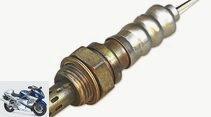
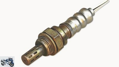
Lambda probe: This component is located in the exhaust manifold and regulates the injection quantity based on the residual oxygen content.
mps photo studio
2/9
Cook
3/9
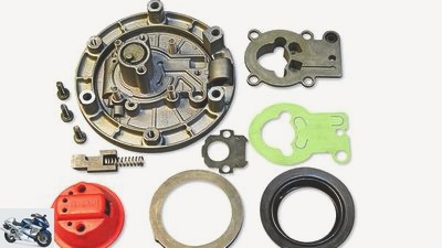
Tank cap in detail: With an integrated ventilation system, such a bland tank cap with its membrane system (green rubber) is quite complicated.
Cook
4/9
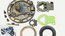
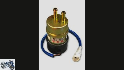
Petrol feed pump: In order to guarantee an even fuel level in the float chamber, some manufacturers used feed pumps between the fuel tap and the carburetor, which can usually be temporarily bridged in the event of a failure thanks to the drop height.
Cook
5/9
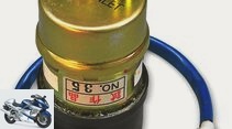
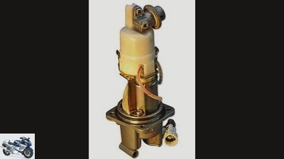
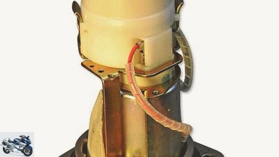
Gasoline pressure pump: Electronic injection systems are supplied by a pressure pump usually located in the tank.
Cook
6/9
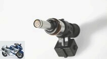
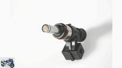
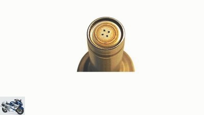
Spray hole discs: A four-hole nozzle, …
Cook
7/9
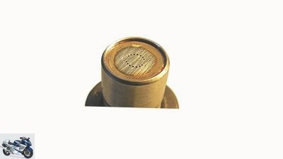
… the 14-hole version with the finest spray jet.
Ducati
8/9
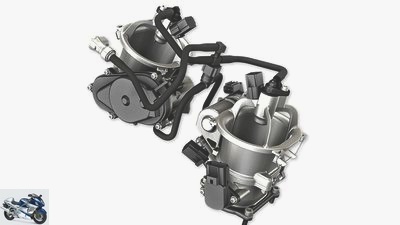
Two-nozzle system: In high-performance engines, in addition to the nozzle in the intake pipe, a second shower nozzle is often used above the throttle valve, which works at high speeds and / or wide-open throttle valves. Both are supplied by the same pipeline system.
BMW
9/9
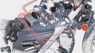
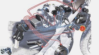
Injection sensors: The information from the sensors (red lines) such as air / water temperature or the values of the lambda probe feed the control unit (ECU), which derives the commands (blue lines) for the injection quantity or, in the event of overheating, the activation of the fan.
counselor
technology & future
Mixture formation
PS-Technik series part 9
Fuel supply, injection, mixture formation
Content of
The designers pull out all the stops to ensure that the mixture of air and gasoline arrives in the combustion chambers in the optimum ratio and well mixed.
Werner Koch
December 19, 2013
Open the lid and put the expensive juice in. There is hardly a more compact way to store energy than with hydrocarbon connections-
dung from the pump. In addition, the fuel with a density of around 0.72 kilograms per liter is also very light – which delights the weight fetishists to the greatest extent. On the way to the combustion chamber, the fuel goes through a few more stations, without which nothing works. Believe it or not, it starts with the fuel filler cap.
Buy complete article
PS-Technik series part 9
Fuel supply, injection, mixture formation
5 pages) as PDF
€ 2.00
Buy now
On the one hand, it has to seal the tank as tightly as possible in the event of a fall or tipping over to prevent the fuel, which is flammable in a flash, from leaking out. Which in itself wouldn’t be a problem if the tank didn’t have to be vented and vented at the same time. Vented when the fuel expands under heat and the outgassing of certain substances creates an overpressure. Many a tank does this with more or less quiet whistling or hissing. Good thing, because otherwise the tank would leak under the pressure or, in the worst case, burst. Conversely, the tank cap or the ventilation must be designed in such a way that it not only relieves the overpressure, but also prevents a vacuum. This occurs when there is less fuel and the missing volume is not compensated for. So the tank ventilation has to work in both directions and still seal sufficiently. What is achieved by a fine labyrinth system and / or ball valves.
workshop
PS technology special
Further training for motorcyclists
read more
The good old carburetor
Motorcycles were usually equipped with carburettors until the 1990s. The petrol only reached the nozzle system through the so-called drop height, the tank had to be well above the float chambers. If the tank ventilation was defective or blocked, the fuel pressure dropped so far that the float chambers were only minimally filled, the mixture was no longer ignitable or the necessary internal cooling of the piston crown or valves failed. Heat collapse or piston jamming were the result. Some manufacturers installed small, lightweight feed pumps on carburetor engines, which ensured a constant level in the float chamber with minimal but constant pressure even when the tank was almost empty. Because of the decreasing tank volume, the fuel pressure in front of the float valve is also reduced, which leads to a slight drop in the fuel level in the float chamber. Nevertheless, the ingeniously simple carburetor delivered flawless running behavior with carefully thought out jets. So it is no wonder when many motorcyclists remember the buttery smooth load changes and the jerk-free throttle response of their old machines with nostalgia. Especially since many a carburettor engine already showed astonishing fuel consumption figures 20 years ago.
For an effective function of the catalytic converter and a good exhaust gas behavior, however, the good old carburettor was no longer useful, the electronic injection found its way into motorcycle construction across the board. In combination with all imaginable sensors and lambda measurement technology, current motorcycle engines manage the balancing act between the strictest emission regulations and brutal performance, the whole thing garnished with an acceptable response behavior and low consumption. A masterpiece, behind which in all cases there is an unbelievably high amount of work in coordination and optimization of the combustion processes, in technical jargon thermodynamics. So it is not surprising that the electronics and injection specialists labor on the electronic motor mapping of newly developed machines until shortly before the market launch – and sometimes even beyond. But that’s a whole different story.
The path of the firewater from the tank to the combustion chamber
Let’s set out to trace the path of the firewater from the tank to the combustion chamber. The start is in the petrol pressure pump, which is housed in the tank and sucks in the fuel at the bottom of the tank via an electric motor and then presses it with three to eight bar pressure via a stable, fabric-reinforced line from the tank to the injection nozzles. When the ignition is switched on, most modern injection engines emit a faint humming sound that stops abruptly when the necessary injection pressure is reached. In order to be able to build up the necessary working pressure, the battery must supply sufficient on-board voltage. If this is too low, there may well be starting problems even though the engine is cranked by the electric starter.
Cook
Electronic injection systems are supplied by a pressure pump that is usually located in the tank.
As soon as the fuel pump is fully operational, all injection nozzles are pressurized with the necessary pressure. In the meantime, all the sensors have delivered their information to the control unit, the so-called ECU (Electronic Control Unit). For a cold start with the throttle / throttle valve closed, a larger amount of fuel is required than with a warm engine. If this enrichment was still operated manually with the choke in carburettor engines, the temperature sensors of the cooling water and intake air give the signal for more fuel with electronic injections. Why? Because, regardless of whether it is a carburetor or an injection, the small droplets of fuel settle on the cold walls in the aluminum cylinder head. One then speaks of a wall wetting. The fuel particles deposited in the intake manifold lead to a leaner gasoline / air mixture and even to the point where it cannot ignite (engine misfires, uneven running). In this operating state, the amount of fuel injected must therefore be increased in order to guarantee smooth running.
But even at higher speeds and with load changes, the fuel deposits on the duct walls often cause problems for the engine engineers. This occurs when the wall wetting is torn off by the sudden negative pressure in the intake duct when the throttle valve is closed, reaches the combustion chamber and there causes a rapid increase in the hydrocarbons in the exhaust gas. You have to know that the majority of the coordination work is not needed to increase performance, but to reduce harmful substances in the exhaust gas. First and foremost, it is important that the fuel supplied is burned as completely as possible in all operating states.
Reduction of harmful substances in the exhaust gas
The basis for this is the best possible mixing of gasoline and intake air, whereby the position of the injection nozzle and the atomization play a decisive role. The injection jet must be designed in such a way that, under dynamic conditions, it is aimed at the inlet valve as directly as possible and without touching the wall. However, since the air flow changes depending on the speed and throttle position, the engineers have to be satisfied with the best compromise here too. Due to the extremely short period of time (around 4/100 seconds at idle, 4/1000 seconds at 12,000 rpm) and the short distance from the injection nozzle to the inlet valve (110 to around 160 millimeters), this is not always possible. In order to finely atomize the fuel during the injection process, it is pressed through so-called injection perforated disks. The injection needle only rises about 0.5 millimeters from its seat, under which the small, punched holes take over the distribution and the direction of spraying of the fuel. The longer the opening time, the richer the mixture and vice versa.
The last but very efficient way of mixing fuel and air is the swirl that occurs when the mixture hits the piston and turns there in a proper loop. In this air vortex, the fuel particles evaporate due to the turbulence and the high air temperature and are then ignited by the spark plug in the best-resolved mixture. More details on the complex engine electronics can be found in episode 17.
Related articles
-
Adjusting the carburetor: the correct mixture composition
Schermer counselor workshop Adjusting the carburetor: the correct mixture composition Adjust the carburetor This is how the correct mixture composition…
-
Schoch 49 pictures Schoch 1/49 If the engine does not immediately idle when you let go of the throttle grip, the ability of the throttle cable to operate…
-
Carburetor functionality in the video
Smartereveryday 49 pictures Schoch 1/49 If the engine does not immediately idle when you let go of the throttle grip, the ability of the throttle cable…
-
Restoration of the BMW R 80 G-S, part 3 structure, carburetor, electrics
Photo: Koch 10 pictures Cook 1/10 There are reasons why the R 80 G / S is back in the workshop after just a few hours. More about this in the MOTORRAD…
-
17th pictures archive 1/17 The BMW F 800 engine, with its oil ducts running through it, shows how complex the pressure circulating lubrication is….
-
Technology: injection electronics
K counselor technology & future Technology: injection electronics Technology: injection electronics What’s humming there?? Content of When five-year-olds…
-
Guide: Injection on a motorcycle
Drawing: Schermer counselor technology & future Guide: Injection on a motorcycle Guide: Injection on a motorcycle Find and rectify faults in the…
-
Honda NC 700 S in the test: the entry-level motorcycle from Honda
Artist 12th pictures Honda 1/12 Honda NC 700 S – The naked bike is powered by an in-line two-cylinder engine of 670 cubic meters. Honda 2/12 Honda NC 700…
-
MotoGP technology: valve trains
counselor workshop MotoGP technology: valve trains MotoGP technology: valve trains Sex offender Stoner? Traction control? Tire technology? Happiness? It…
-
Tips for mechanics: Maintenance of motorcycle cooling systems
Ralf Petersen 15th pictures Ralf Petersen 1/15 We explain how the maintenance of a cooling system works. Ralf Petersen 2/15 This is needed for…