Table of contents
- PS-Technik series part 7 Transmission and gearshift
- 0.10 seconds for the pure switching process
- Conversion of the rotary movement on the gear lever
- Lightweight components against inertia
- Racing gearbox vs. touring gearbox
- Smoothest running on gear wheels with helical teeth
- The greater the gear spread, the harder the shifting process
- Gear damage
- Tips and Tricks
Mitterbauer
22nd pictures
Cook
1/22
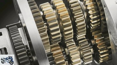
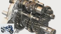
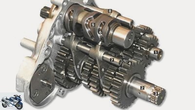
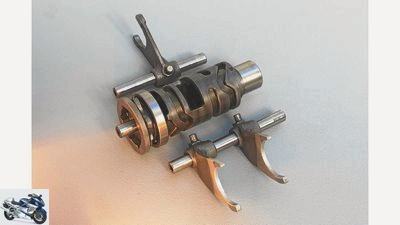
Gearbox components: The gearbox input shaft (1) transfers the power to the output shaft (2). The chain pinion is attached to the end (3). A gear pair (4) is available for each gear. When changing gears, the shift drum (5) rotates about 45 degrees. The milled grooves (6) move the shift forks (8) mounted on a shaft (7).
fact
2/22
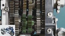
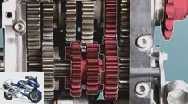
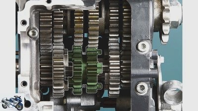
… and the connection via the intermediate idle (no power transmission possible) …
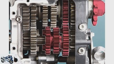
fact
3/22
… to the right idler wheel. Thanks to the free angle of rotation of the claws, the wheel can lock into place quickly and safely even if the gear wheels differ in speed.
Cook
4/22
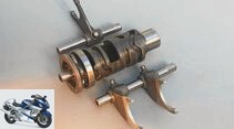
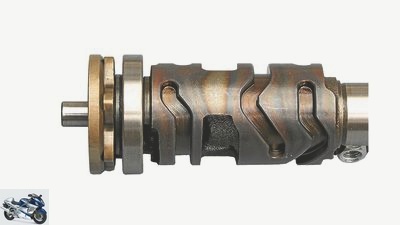
Shift drum and shift forks transform the rotary movement into an axial displacement.
Cook
5/22
Link guide: The function of the grooves in the shift drum can be clearly seen during processing …
Cook
6/22
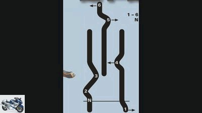
… The offset of the middle groove (shift fork gear 5 and 6) results from the offset of the shift shafts to each other. The shift forks for gears 1 to 4 sit on a common shaft. (N = idle).
Cook
7/22
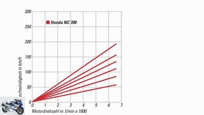
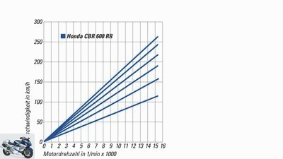
… With the NC 700, this gear step spreads significantly more than from 4th to 5th gear and is therefore a real, speed-reducing overdrive gear step.
Cook
8/22
Gear diagrams: They clearly show how the progressively narrowing spread of the Honda CBR 600 RR sports transmission differs from the more touristy Honda NC 700, which is designed for low consumption. While the jump from 5th to 6th gear is very small on the sports transmission, …
Bilski
9/22
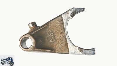
Gearbox damage: The hard chrome-plated contact surfaces of the shift fork show slight scuff marks due to the lateral forces of the gears.
Cook
10/22
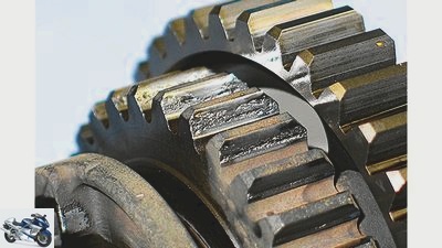
Breakouts on the surface (pitting) usually occur on the gears with the longest engagement time.
fact
11/22
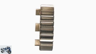
The switching process shows how the double sliding wheel is pushed out of the left idler wheel in the first step …
Cook
12/22
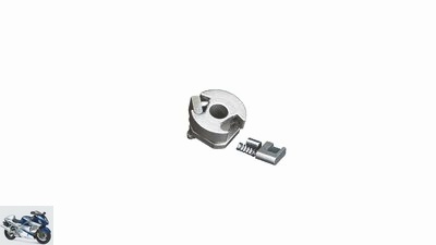
… The relief grinding of around four degrees guarantees reliable toothing under heavy loads.
fact
13/22
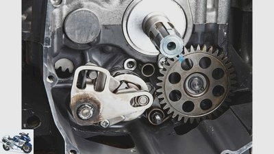
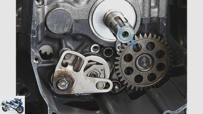
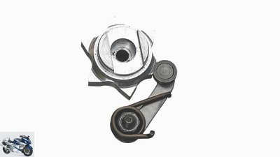
Automatic gearshift: This component transfers the movement from the gearshift shaft to the gearshift drum, …
fact
14/22
… is equipped with a spring-loaded ratchet mechanism …
fact
15/22
… and allows the gear lever to spring back to its original position.
Cook
16/22
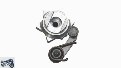
Star switch: neutral position, fixed by the raised recess …
Cook
17/22
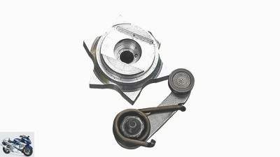
… First gear is engaged …
Cook
18/22
… Position when changing gears, the spring-loaded roller and the inclined cam accelerate the shift drum.
Cook
19/22
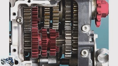
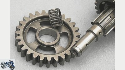
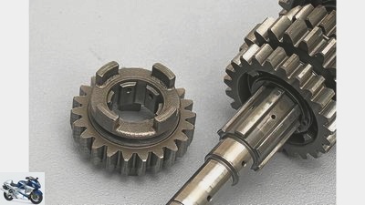
Idler gears rotate freely on the gear shaft in needle bearings or on sliding bushes. Each idler gear is combined with a sliding or fixed gear on the opposite gear shaft.
Cook
20/22
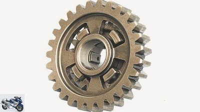
Sliding wheels are connected to the gear shaft (right) via internal gearing (left) and can be moved axially. The claws on the circumferential groove for the shift fork engage the adjacent idler gear.
Cook
21/22
Shift claws engage in the recesses of the idler gear and ensure the frictional connection to the transmission shaft …
Cook
22/22
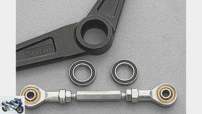
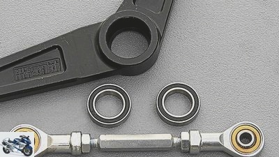
Tips and tricks: Sealed ball bearings and high-quality ball joints make the switching process more precise and easier.
counselor
technology & future
Gear shift
PS-Technik series part 7
Transmission and gearshift
Content of
Hardly any motorcyclist thinks about changing gears every second with a short step. It pushes, turns, clicks and clicks violently in the switch box.
Werner Koch
October 15, 2013
A short step – clack – walk in and off you go. But how does the gear wheel get into position in a fraction of a second? And how is it guaranteed that in a rush, two gears do not engage at the same time, which would mean a disaster for the transmission and the driver. In addition, the question arises as to how the variable gear wheels survive the brutally hammering engine power in connection with sloppy shifting operations?
Buy complete article
PS-Technik series part 7
Transmission and gearshift
6 pages) as PDF
€ 2.00
Buy now
workshop
PS technology special
Further training for motorcyclists
read more
0.10 seconds for the pure switching process
In order to understand what goes on in a conventional motorcycle claw transmission, we rewind the gearshift process in slow motion and observe how the rotary movement on the gearshift lever develops into an axial displacement of the gears. The first gear is turned out, the maximum torque ensures rapid acceleration. Shortly before the red zone, i.e. the maximum engine speed, the driver takes off the gas, pulls the clutch and shifts into second gear. He moves the gear lever up around 30 millimeters – or down in the case of a racetrack configuration. Tough pilots need around 0.15 seconds for the clutch to re-engage, the interruption of tractive power is over and the throttle valves are at full throttle.
For the actual shifting process, on the other hand, only about 0.10 seconds pass, in which the first gear is moved out of its position and then the second gear wheel is axially shifted about six millimeters on the transmission shaft so that the shift claws engage securely.
Conversion of the rotary movement on the gear lever
A few mechanical steps are necessary to convert the rotary movement on the gearshift lever into a linear displacement. First of all, the rotary movement of the selector shaft must be transmitted to the selector drum. There are different possibilities for this in the form of teeth, a lever transmission or a pawl mechanism. All systems are equipped with a ratchet mechanism that allows the selector shaft to turn the selector drum by certain degrees and then return to its original position. Only the grooves milled into the shift drum transform the rotation into a linear movement and transport the so-called sliding wheels through the link on the shift drum into their position.
Due to the lightning-fast processes of the mechanical process, friction and inertia forces arise. Neither of these can be used at all with sports and racing machines, because there an unnecessarily long interruption of tractive power on the rear wheel causes suspension unrest and loss of time. In high-quality sports engines, the shift shaft and shift drum rotate in needle or ball bearings in order to reduce friction as much as possible. In professionally built racing machines, needle-bearing gear levers and backlash-free, smooth-running quality ball heads or even needle-bearing gearshift rods reduce friction and play in the gearshift construction to a minimum.
Lightweight components against inertia
The inertia in the gearbox can be tackled with lightweight components. The steel shift drums are mostly hollow cast and / or largely milled off. Shift drums made from a high-strength aluminum alloy are even more efficient. These allow the roller to rotate at lightning speed, which is supported by the so-called star switch. This has the task of locking the shift drum absolutely reliably through the cam profile and a spring-loaded roller. Pointed cam shapes also ensure that the spring force accelerates the shift drum when the gear wheel is engaged, thus shortening the shifting process.
Cook
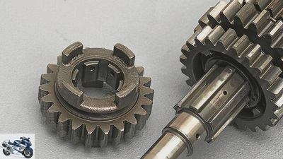
Sliding gears are connected to the gear shaft (right) via internal gearing (left) and can be moved axially.
The gearbox itself consists of the so-called input shaft, on the end of which the clutch sits and introduces the force, and the output shaft, the end of which protrudes from the motor housing and accommodates the chain pinion. A pair of gears is available for each gear stage. Since these are constantly in engagement, these pairings must each consist of a fixed gear and an idler gear. Loose gears are not permanently connected to the shaft, but rotate freely on needle or plain bearing bushes on the respective gear shaft. The fixed gears are rigid, non-displaceable gears that are milled or pressed onto the shaft. The frictional connection to the shaft is created by the sliding wheels, which can be shifted laterally on a toothing and which engage with the claws in the recesses of the idler gears.
This also gives the idler gears a form-fitting connection in the drive train. The problem with the double sliding wheels is their high weight, which releases enormous inertia forces when shifting quickly, which is why the shift forks must have a high level of flexural rigidity.
Racing gearbox vs. touring gearbox
The gear ratios of the respective gear steps depend on the intended use and the engine characteristics. Sports and racing transmissions are designed in such a way that all gears can be used on the racetrack in order to keep the speed jumps when shifting as low as possible. So the first gear is geared relatively long, the remaining levels are designed increasingly narrow. This guarantees that you can stay in the most favorable torque and power range at high speed and correspondingly high driving resistance (air resistance plus rolling resistance). Touring machines, on the other hand, are increasingly being equipped with a noticeably long sixth gear, which significantly reduces the speed and thus saves material and fuel.
Smoothest running on gear wheels with helical teeth
The tooth shapes of the gear wheels are decisive for the quietest possible running of the gear. The combination of pressure angle, profile shift, module and countless other factors is more likely to be traded as a trade secret. Gear wheels with helical teeth undoubtedly have the smoothest running. Such transmissions, however, require a completely different type of gear shift, with the power flow not being established via sliding gears but via so-called shift sleeves. The advantage of gearshift sleeves: Due to their low weight, they can be moved extremely quickly and easily, which is why such transmissions are particularly difficult in racing. The disadvantage: The gear shafts are a little longer than with claw gears, in which the entire gear wheels are shifted.
Cook
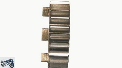
The relief grinding of around four degrees guarantees reliable toothing under heavy loads.
The shiftability of a transmission depends on many factors. In addition to the mechanical friction already mentioned, the shift curve on the shift drum and the arrangement and free angle of rotation as well as the number of claws play a major role. After all, they have to change their position at full gear speed – around a third of the engine speed. In order to guarantee that the gear wheels remain firmly in their position, the claws of high-performance machines are provided with a relief of around four degrees. This relief ensures that the gear wheels connected to one another literally “tighten” under load..
In purely mathematical terms, a resistance-free shifting process is only possible after every second gear change. Namely when the claws are exactly aligned with the recesses on the adjacent gear wheel. If this is not the case, the shift fork pushes the gear wheel into the so-called “claw-on-claw” position, which delays the shifting process until the gear wheels have rotated so far that the claws can slip into one another. The greater the free angle of rotation, ie the “play” from claw stop to claw stop, the greater the chance of a clean shifting process. With the disadvantage that this play has a negative effect on the load change behavior. That is why the designers usually look for the best compromise between easy shiftability and direct, low-jolt power transmission.
The greater the gear spread, the harder the shifting process
As a rule, the larger the gear spread, the harder the shifting process. The reason: The large speed difference between the engaging gears prevents a more or less synchronous run, the claws rattle correspondingly hard into the recesses. The situation is similar with many machines when engaging first gear, which often arouses the attention of passers-by with a loud, hard gear shift. Most of the time, the main cause of this mishap is a clutch that has stuck to the engine oil.
The engine flywheel mass, the drag torque between the crankshaft and the rear wheel – keyword sticky clutch – and the shock absorbers in the drive train also influence the shifting process depending on the engine speed. Rapid upward gear changes are definitely possible without using the clutch; after all, a brief release of the load on the drive train is enough to shift the gear wheels. However, such a switching process does not always succeed, which means that the claws engage hard and with a loud switching impact. On the other hand, good electronic switching devices regulate this process almost perfectly. However, it is not enough to simply turn off the ignition for a few milliseconds. Only when the engine speed and shift position are taken into account can clever electronics, which, for example, trigger an intermediate spark, not only shorten the shift process to around 2/100 seconds, but also protect the transmission and stabilize the chassis when accelerating. How the engine power is transmitted to the rear wheel via the chain and cardan and how the torque affects the swing arm, suspension and cornering behavior, is in PS 12/2013.
Gear damage
Bilski
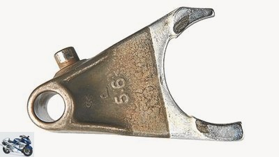
Gearbox damage: The hard chrome-plated contact surfaces of the shift fork show slight scuff marks due to the lateral forces of the gears.
If the edges of the shift claws are worn and properly rounded, then the sliding wheels are pushed outwards against the guide of the shift fork under load. The result: the gears can jump out, the shift forks rub against the guide surfaces or bend. This triggers a chain reaction that ends in the fact that the gear wheels and gearshift forks have to be replaced.
Surface chipping, known as pitting, is one of the most common gear damage. The causes are mostly too small dimensions, wrong hardening process or unfavorable tooth shapes. In continuous operation, such gears are destroyed by the high surface pressure.
Tips and Tricks
Cook
Sealed ball bearings and high-quality ball joints make the switching process more precise and easier.
In order to optimize a series connection, you should first check whether the shift linkage is at a 90-degree angle to the shift lever. This is the only way to ensure the leverage of the kinematics specified during construction.
The often cheap ball joint heads can be replaced by high-quality and smooth-running components (e.g. Askubal, Durbal, SKF). To do this, the standard bolts may have to be drilled out of the shift levers.
Shift levers with smooth-running and play-free ball bearings (HH-Racetech) improve shifting feel and ease of movement. Shift levers positioned far outside the footrest axis also interfere with smooth gear changes, since the planes of rotation are too far apart and the boot has to slide over the shift knob to compensate for the length.
Related articles
-
Kawasaki 6th pictures Cook 1/6 PS technology expert and motorcycle whisperer Werner “Mini” Koch is constantly tinkering and tinkering himself in his own…
-
counselor workshop Adjust shift and brake levers Adjust shift and brake levers Adjust shift and brake levers The levers have to be positioned correctly…
-
to travel Motorcycle gear Motorcycle gear Either way Regardless of whether it’s a light sport enduro or a heavy touring steamer – whoever goes on a long…
-
Triumph Speed Twin recall: shift linkage can come loose
triumph. counselor traffic & business Triumph Speed Twin recall: shift linkage can come loose Triumph Speed Twin recall Shift linkage can come loose…
-
Aprilia RSV4 RF correctly tune setup landing gear
jkuenstle.de 28 pictures jkuenstle.de 1/28 Comparison test Aprilia RSV4 RF vs. Kawasaki H2R. jkuenstle.de 2/28 Space design: at speeds of well over 300…
-
fact clothing Station wagons, jackets & pants Practical advice: rain gear Practical advice: rain gear Drop by drop cheerful No question about it,…
-
Electronic landing gear under the microscope
www.bilski-fotografie.de 15th pictures Jacek Bilski 1/15 Chassis are the link between the road and the motorcycle. So far, they have usually been set…
-
Bartek Zaranek 14th pictures Bartek Zaranek 1/14 Actually, an enduro should be built. Bartek Zaranek 2/14 But then it turned out to be a supermoto….
-
Orth Sports & scene Style – head gear oil 10 T 30 Style – head gear oil 10 T 30 The schnapps idea Content of Almost more important than just having an…
-
SW Motech Legend Gear 2019 Harley-Davidson
SW Motech accesories Luggage SW Motech Legend Gear 2019 Harley-Davidson SW Motech Legend Gear 2019 Side pockets for Harley models Luggage specialist SW…