Table of contents
- PS technology series part 1 Intake tract and suction pipes
- Intake tract and suction pipes (part 1)
- MotoGP bikes show the way
- Turbochargers and compressors do more and more
- Intake tract and suction pipes (part 2)
- Our 1000cc four-cylinder needs 10 liters of fresh air from the airbox
- The compromise: two long and two shorter funnels
- The S 1000 RR shortens the intake path for all four cylinders
- Performance curves: BMW S 1000 RR & Kawasaki Z 1000
- technical basics
manufacturer


12th pictures
manufacturer
1/12
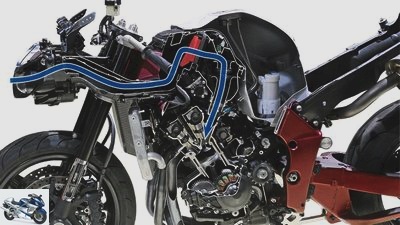
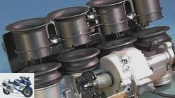
The trick with the pressure: intake tract and intake manifolds.

2snap
2/12
Two louvers on the MotoGP Honda. It is located on the foremost edge of the cladding front for optimal flow.
2snap
3/12
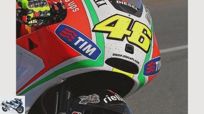
A central inlet on the Ducati Desmosedici. It is located on the foremost edge of the cladding front for optimal flow.
archive
4/12
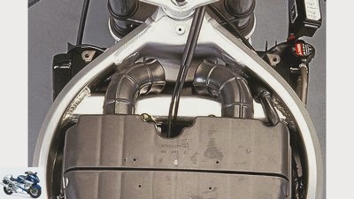
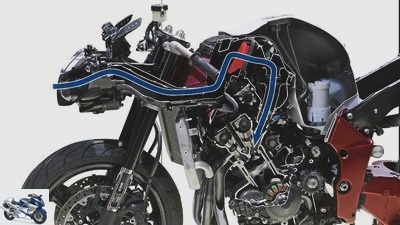
Honda scooped the CBR 900’s intake air from the steering head to the two intake snorkels.
archive
5/12
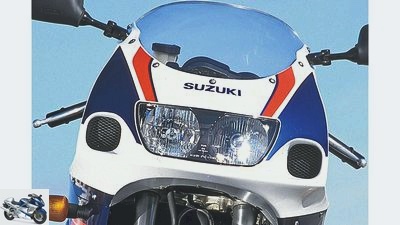
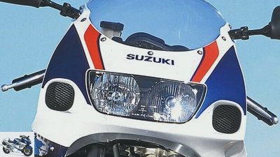
The off-center intake ports were the hallmark of the Suzuki SRAD range in the 90s.
Cook
6/12
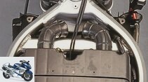
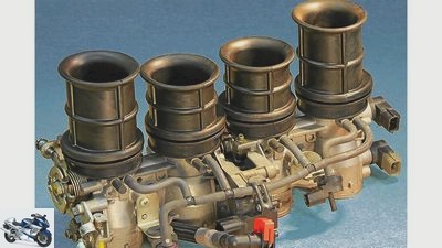
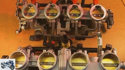
The 45.8 mm intake manifold of the BMW engine (in the front picture) has a 43 percent larger free cross-section than the comparatively tiny 38 mm intake manifold of the Kawasaki Z 1000.
Cook
7/12
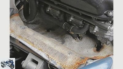
A heat insulation mat between the engine and the airbox prevents the intake tract from heating up in a performance-guzzling manner.
archive
8/12
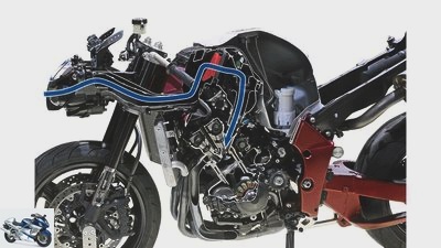
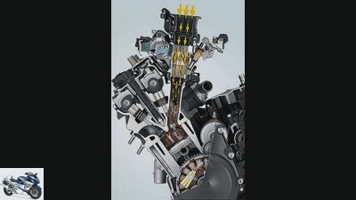
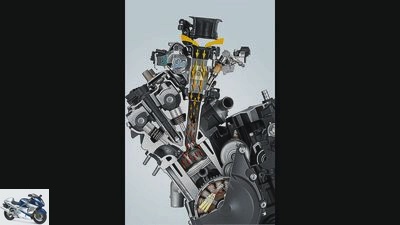
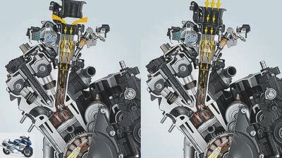
It is easy to see how the pulsating gas column builds up in the long, conically tapering intake tract of the Yamaha YZF-R6 engine. When the upper air funnels suddenly lift off at 13,700 revolutions, the flow breaks down briefly (measurable on the test bench, hardly noticeable in practice). Then the currently most powerful 600 engine rushes ahead unchecked.
archive
9/12
It is easy to see how the pulsating gas column builds up in the long, conically tapering intake tract of the Yamaha YZF-R6 engine. When the upper air funnels suddenly lift off at 13,700 revolutions, the flow collapses briefly (measurable on the test stand, hardly noticeable in practice). Then the currently most powerful 600 engine rushes forward unchecked.
Cook
10/12
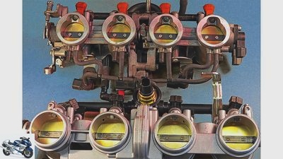
The 56 and 78 millimeter long intake funnels of the Kawasaki Z 1000 are designed to combine pulling power and maneuverability.
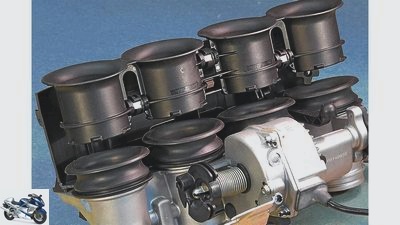
Cook
11/12
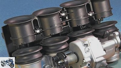
At 11,300 revolutions, the 60 millimeter long funnel of the BMW four-cylinder lift up and reveal the shortened intake path.
Cook
12/12
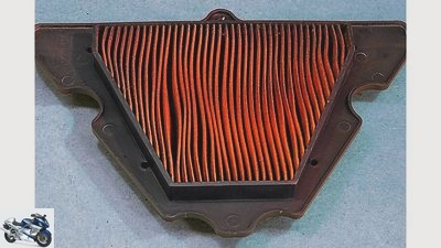
A paper air filter clogged by the oil mist from the engine ventilation system costs performance and an unnecessarily large amount of fuel.
counselor
technology & future
Technology intake manifold
PS technology series part 1
Intake tract and suction pipes
Content of
No performance without air. Whether man or machine: If there is a lack of oxygen, both will work “Internal combustion engines” not moving forward. It is therefore important to feed the engine with plenty of cool air.
Werner Koch
04/17/2013
Intake tract and suction pipes (part 1)
archive
No performance without air.
If you are in a hurry – and naturally designed sports motorcycles are always in a hurry – pull out all the stops. For example, through the best possible air supply into the combustion chamber. Because an internal combustion engine, let’s take a sturdy 1000cc four-cylinder with almost 200 hp liter output as an example, is a real yogurt. If the throttle valves are fully open at a nominal speed of 13,000 rpm (the highest power is available here), the engine swallows 108 liters of air per second from the atmosphere. All sorts of aerodynamic tricks help to ensure that the air flow enters the combustion chamber with as little resistance as possible. For example the one with the back pressure. The engineers use the airflow at high speed in order to convey it into the engine with as little braking as possible.
Buy complete article
PS technology series part 1
Intake tract and suction pipes
6 pages) as PDF
€ 2.00
Buy now
The highest air pressure occurs on the motorcycle where the air flow hits a body head-on and accumulates – hence the word dynamic pressure. On a motorcycle, this is the fairing nose. For this very reason, the air intake to the engine is right at the front of most sports and racing machines. The air pressure is highest there, while the wind pressure on the curves of the front fairing and the windshield clearly decreases, but the friction of the air flow increases. For the most efficient possible back pressure in the air filter box – in German: Airbox – direct flow at right angles is therefore the best solution. Whether the throat is designed in one piece or is distributed over two openings (Honda RCV-MotoGP) is unimportant. The exposed position at the foremost part of the cladding is important. Although it interferes with the aerodynamics of the fairing there, the bottom line is that the increase in performance at high speeds is superimposed on the somewhat poorer drag coefficient (drag coefficient) due to the turbulence that occurs at the opening.
workshop
PS technology special
Further training for motorcyclists
read more
MotoGP bikes show the way

2snap
A central inlet on the Ducati Desmosedici, which is located on the foremost edge of the fairing front for optimal flow.
That is why the alternatives developed in the early days of dynamic pressure technology at the beginning of the 1990s (air duct between steering head and radiator on the Honda CBR 900) or the side openings (Kawasaki ZX-R 750 and Suzuki GSX-R 750 SRAD) have completely disappeared . Even the central, but sloping, back pressure ducts of the Kawasaki ZX-10 R or BMW, which are more due to the design than the function S 1000 RR do not work as efficiently as the clear solutions of the MotoGP bikes.
However, there are still a number of obstacles in the way of the air flow before it enters the cylinder. More or less curved air shafts, edges and corners in the air filter chamber and, last but not least, the air filter itself slow down the oncoming hurricane. Not to mention the only a few square centimeters small annular gap between the valve seat and valve disc. Nevertheless, the trick with the back pressure has established itself in all sports machines.
Of course, the air ducts on thoroughbred racing machines are constructed much more linearly and aerodynamically sophisticated in order to increase the loading effect. The air filters used in MotoGP also work with a significantly lower flow resistance than the components in road machines designed for dusty everyday life.

Super athlete
Suzuki, Honda, Yamaha, Ducati and BMW super sports cars
Generations of athletes from three decades
read more
workshop
Advice: check and adjust steering head bearings
Steering head bearing: the fulcrum
read more
Turbochargers and compressors do more and more
archive
The off-center intake ports were the hallmark of the Suzuki SRAD range in the 90s.
Although the airflow is directed into the airbox at the current speed, the effect is not nearly as high as with mechanical charging by means of a turbocharger or compressor. This is simply due to the fact that the dynamic pressure system is not closed and the airstream can evade the air duct as soon as too high a counter pressure builds up there.
In the case of mechanical supercharging, on the other hand, the charge air is literally pressed into the combustion chamber from the turbine in a sealed line system – in dragster engines with up to four bar.
In purely mathematical terms and under the best conditions, an optimally designed Ramair system brings it to around 18 millibars at 200 km / h and at 300 km / h to around 40 millibars. That’s the theory. According to the real measured values of a factory MotoGP machine, a good dynamic pressure system at around 300 km / h increases the “boost pressure” of just 25 millibars (this corresponds to 0.025 bar). As a rule of thumb, the engine output increases by around one percent for every ten millibars. In the case of the 1000 MotoGP machines with around 260 hp, that would be 6.5 hp. Not the world, but when it comes to the last tenth, every horsepower counts.
Intake tract and suction pipes (part 2)
Cook
The 45.8 mm intake manifold of the BMW engine (front) has a 43 percent larger free cross-section than the comparatively tiny 38 mm intake manifold of the Kawasaki Z 1000 (rear).
Another argument in favor of this fresh air supply is the more or less cool intake air. Because cool air expands less, which means that the amount of oxygen per liter of cool air is higher than that of one liter of heated air. However, the proportion of oxygen measured against the total volume of air does not change. In both cool and hot air, this is around 21 percent.
However, on its way into the cylinder, the cool intake air wanders through some of the areas heated up by the heat from the engine. The airbox, which is usually placed above the cylinder head, and the throttle valve bodies including the funnels are located in the exhaust air flow of the water cooler and the red-hot exhaust manifold and are heated up enormously. As a result, the intake air, which is initially cool, also warms up, with the consequences described above. Clever tuners and designers therefore try to insulate these components as well as possible using an air gap through which fresh air flows and a heat insulation mat.
In order to compare the actual atmospheric ambient air pressure and the air pressure in the intake tract, two sensors are used on modern injection systems, which are supplemented by a thermometer for the intake air and forward this data to the computer for the optimal injection quantity.
A very decisive factor for maximum performance is the degree of filling of the cylinders. In addition to other parameters, this parameter also determines how much air the engine has to suck in at nominal speed under full load. Due to the throttling effect of the air resistance on the way to the airbox and the following, constricted intake duct in the valve area, the four-stroke naturally aspirated engine only manages to fill almost the available individual displacement of the cylinders with an ignitable gasoline / air mixture within a very limited speed range . In the case of our 1000cc four-cylinder engine, each with 250 cm³ individual displacement, the cylinders are filled with about 250 cm³ fresh gas, i.e. 100 percent, at the best degree of filling, or also called the degree of delivery.
A decisive factor in the optimal cylinder filling with a powerful gasoline / air mixture is the geometric design of the airbox, including the air funnel and intake manifolds. The necessary airbox volume depends mainly on the number of cylinders and the ignition angles. Large-volume twins or even single-cylinder engines require dramatically larger air filter boxes in relation to the stroke volume than uniformly inflowing multi-cylinder engines.
landing gear & Spring elements
Guide: Adjusting the suspension / damping correctly, part 1
Adjust the suspension on the motorcycle
read more

workshop
Adviser: the battery
Everything about the battery
read more
Our 1000cc four-cylinder needs 10 liters of fresh air from the airbox
archive
Honda scooped the CBR 900’s intake air from the steering head to the two intake snorkels.
As a rule of thumb, the following applies: In a 1000cc four-cylinder engine that fires symmetrically every 180 crankshaft degrees, the air filter chamber should have ten times as much volume as the engine, i.e. ten liters. A two-cylinder 500 engine needs 20 times, a 250 single cylinder even 40 times the stroke volume, i.e. ten liters each, for optimal power output.
The geometry of the intake manifold also has clear rules: long intake manifolds with a small diameter increase the filling at low and medium speeds, but inhibit the air flow at high speeds and thus impair maximum performance.
Maximum performance is only possible with short suction pipes in conjunction with large diameters, as this configuration allows a large gas throughput at high speeds. With the disadvantage that the engine loses power and therefore torque at low and medium speeds.
The compromise: two long and two shorter funnels
Cook
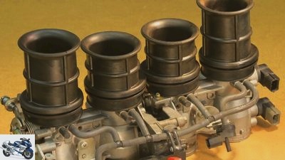
The 56 and 78 millimeter long intake funnels of the Kawasaki Z 1000 are designed to combine pulling power and maneuverability.
Why? Because the gas column pulsing in the intake manifold builds up too low a speed and inertia at low speeds. This inertia means that the sucked in gasoline / air mixture (which can reach up to 500 km / h in the area of the inlet valve) still flows into the combustion chamber when the vacuum in the cylinder decreases. This is the case when the piston has reached bottom dead center or is already moving upwards again. One then speaks of a gas-dynamic charging effect. Unfortunately, this vibration system, which is dependent on length and diameter, among other things, only works optimally in a certain speed range. The logical conclusion: the technicians try to adapt the desired resonance to the respective speed with variable intake manifold lengths. Huge pipe and resonance body systems are built into the car engines for this purpose, which generate the widest possible torque range via electronically controlled flaps. For reasons of space alone, such tricks are hardly possible with motorcycles.
The only viable alternative is currently the variable intake funnel lengths, which usually work in two stages. The extended version for the lower speed range, the short version for high speeds and maximum power. The simple variant of funnels of different lengths is that in a four-cylinder engine, two long and two shorter funnels are installed in order to make the engine a compromise between pulling power and maneuverability. A simple and inexpensive method with a comparatively modest effect.
workshop
Advisory: clean the carburetor
Clean the carburetor
read more
technology & future
Adviser: change spark plugs
Everything about spark plugs
read more
The S 1000 RR shortens the intake path for all four cylinders
Cook
At 11300 revolutions, the 60 millimeter long funnel of the BMW four-cylinder lift up and release the shortened intake path.
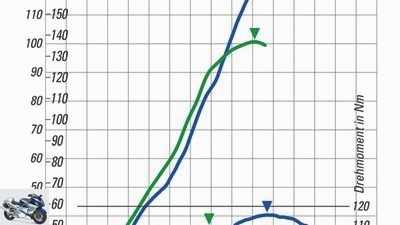
The engines of the BMW S 1000 RR and the Kawasaki Z 1000 represent. Very similar in its basic structure, the Kawasaki engine puts an impressive torque curve on paper, which is also very impressive when surfing country roads. However, when things get down to business and the BMW four-cylinder unpacks the club, the Kawasaki simply takes its breath away.
Preview: In the second part of the PS-Technik series, we make ourselves very small and slip into the high-performance department of fast motorcycle engines as channel workers between camshafts, valves and combustion chamber.
Performance curves: BMW S 1000 RR & Kawasaki Z 1000
archive
Performance curve BMW S 1000 RR (blue) and Kawasaki Z 1000 (green).
Up to around 8000 rpm, the Kawasaki engine (green), which is equipped with a comparatively slim intake system, has significantly more torque than the BMW drive (blue) with its huge intake manifolds. Then the performance curve of the naked bike flattens out, while the BMW S 1000 RR, trimmed for maximum performance, unpacks the hammer. At 10,400 revolutions, the intake paths are shortened in order to draw as much gasoline / air mixture as possible into the combustion chamber through the lowest possible flow resistance. The nominal speed is 3000 rpm higher than the Kawasaki Z 1000 engine. Of course, in addition to the intake geometry, valve control, compression and the bore / stroke ratio also play a role in the development of power.
technical basics
manufacturer
The gas column in the long, conically tapering intake tract builds up (right). From 13700 rpm, the upper ventilators suddenly lift off (left) and the flow briefly collapses.
The air sucked in from the earth’s atmosphere provides the oxygen required for combustion. This consists of around 21 percent oxygen, the remaining volume is made up of nitrogen (approx. 78 percent), the noble gas argon (just under one percent) and other gases. Air is colorless, odorless and tasteless. Under normal conditions, one cubic meter of air weighs 1.293 kilograms. In order to mix the desired mixture with the lambda value 1.0, the mass ratio of fuel to air should be 1: 14.7.
To burn one liter of fuel (density on average around 0.75 kilograms), 14.7 kilograms of air are required. Since one cubic meter of air weighs 1.293 kilograms, the engine has to suck in around 19 cubic meters of air to burn one liter of fuel.
In the case of a richer mixture with a lambda value of 0.9, consumption and exhaust gas values deteriorate, but performance increases. Dynamic pressure occurs where a flow hits a body and applies a certain pressure to it. The highest dynamic pressure is usually in the foremost area of the body against which the flow occurs, where it also generates the highest air resistance.
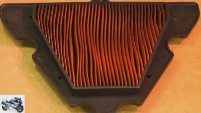
Cook
A paper air filter clogged by the oil mist from the engine ventilation system costs performance and an unnecessarily large amount of fuel.
In order to shield the waste heat from the engine as much as possible from the intake tract, i.e. the airbox and throttle valve body, every skilled sportsman can optimize his motorcycle accordingly. A thermal insulation mat inserted as a large-area partition between the cylinder head and the intake tract keeps a large part of the rising heat away and can definitely increase the performance in a measurable range. The inserted insulation mat should protrude two centimeters after adjustment so that the fibrous edges can be folded over and sewn or glued.
The air filter box and intake snorkel can also be glued directly with a self-adhesive insulation mat. The same applies to the bottom of the tank, which is insulated and prevents the fuel from heating up, which has an effect similar to that of heated air. Source of supply for both mats: the specialist trade or racing specialist G&L motorcycle technology (www.gl-motorradtechnik.de).
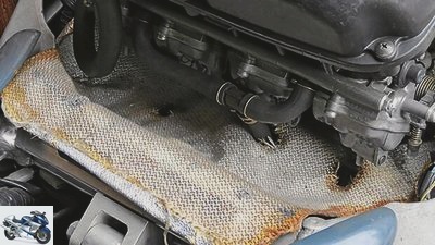
Cook
A heat insulation mat between the engine and the airbox prevents the intake tract from heating up in a performance-guzzling manner.
However, it is important to ensure that the insulation mat leaves enough space so that the hot exhaust air from the motor can flow out to the rear. A look at the air filter insert on sports machines that are squeezed out on the racetrack can’t hurt. The air on the racetrack is only a little dustier for brief moments than on the country road when things are going badly, but the permanently high speeds can also pump engine oil in the form of a fine mist into the airbox via the vent. If this oil mist settles in the standard paper air filter, it can actually stick together and increase the air flow resistance. The result is less power and more fuel consumption. So throw it away, because blowing it out and knocking it out is only considered improvisation.
The situation is different with special cotton filter nets, which are oiled for perfect cleaning with often less flow resistance (BMC, K.&N, etc). If necessary, these can be washed out and moistened with a little air filter oil and reused several times.
Related articles
-
Technology: BMW S 1000 RR engine in detail
BMW 13th pictures Artist 1/13 The on-board tool kit of the BMW almost ties in with old traditions. With the help of the nine-part set you can strip the…
-
This is how the new super sports technology works
Suzuki 20th pictures Suzuki 1/20 The Suzuki GSX-R combines high tech with clever engineering. Suzuki 2/20 This centrifugal force mimic adjusts the timing…
-
Technology Superbike developments
Suzuki 16 pictures archive 1/16 Variable valve control Suzuki GSX-R 1000/2016. archive 2/16 Suzuki engine technology in detail: low speed. archive 3/16…
-
Guide: Technology – engine lubrication
BILLION counselor workshop Guide: Technology – engine lubrication Guide: Technology – Motors and Drive Everything about engine lubrication To ensure…
-
Technology of the new 600 super sports car
counselor technology & future Technology of the new 600 super sports car Technology of the new 600 super sports car New base The new 600 super athletes…
-
New Supersport Motorcycles 2015 Technology Comparison – Part 1
Photos: Manufacturer 16 pictures manufacturer 1/16 At Aprilia everything is different: the V4 spreads its cylinders at a 65-degree angle in order to save…
-
MotoGP technology: valve trains
counselor workshop MotoGP technology: valve trains MotoGP technology: valve trains Sex offender Stoner? Traction control? Tire technology? Happiness? It…
-
PS-Technik reader question Mount heat protection on the manifold
Cook counselor technology & future PS-Technik reader question Mount heat protection on the manifold Technology: Mount the heat protection on the manifold…
-
motorcycles Enduro Technology Honda CRF 450 R Technology Honda CRF 450 R For the sake of simplicity Why complicated when it can be made easy? This is…
-
Technology: injection electronics
K counselor technology & future Technology: injection electronics Technology: injection electronics What’s humming there?? Content of When five-year-olds…