Table of contents
- PS technology series part 3 Cylinders, pistons, connecting rods
- The detonation
- More than five tons of peak pressure
- Pistons neither round nor cylindrical
- The cylinders
- Friction eats up performance
- Connecting rods only bring the force to rotate
- Material alloy and manufacturing process
- Technical basics and tips
- Tips and Tricks
fact

15th pictures
1/15
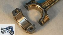
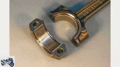
The conventional connecting rod, on the other hand, is machined in several steps and fixed with a fit. The two connecting rod bearing shells are fixed in small, milled grooves to prevent them from twisting.
2/15
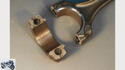
“Cracked” Conrod foot from BMW: The bearing bore is opened by a forced break, which means that the break points are given a perfectly fitting structure and do not require fitting sleeves.
3/15
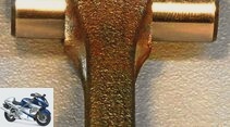
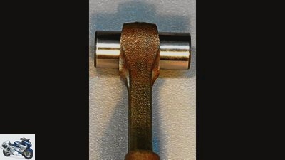
The connecting rod caps are fastened with so-called expansion bolts, which may only be used once. To save weight, the upper eye is tapered in a trapezoidal shape and does not require a bearing bush.
4/15
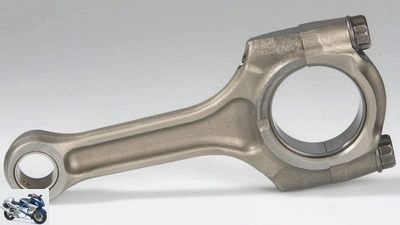
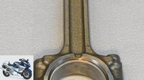
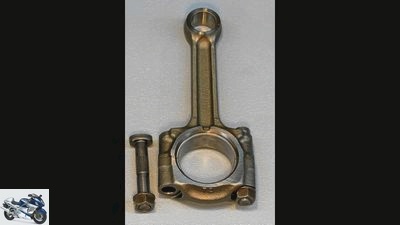
Here the slimmer counterpart of the Kawasaki Z 1000. Around one third of the connecting rod weight is attributed to the oscillating masses (up and down) and two thirds to the rotating (turning) masses. Like the pistons, the connecting rods are also weighed to within a few grams and assigned to a specific weight class with markings.
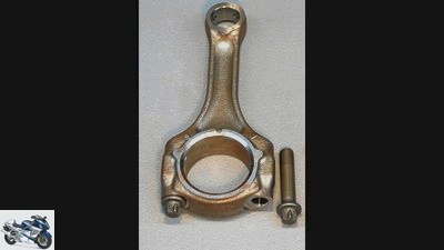
5/15
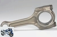
The connecting rod of a BMW S 1000 RR. The smooth transition from the connecting rod to the lower eye is characteristic.
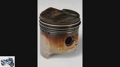
6/15
A so-called full shaft piston for a two-valve engine (recesses on the piston crown), as they were used until the 1980s.
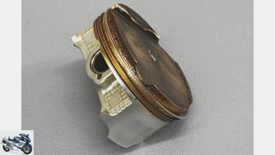
7/15
A large-scale cast piston after 50,000 kilometers. Hardly any wear or damage, only the completely normal oil carbon deposits are noticeable.
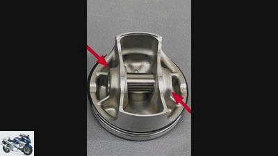
8/15
The forged piston, on the other hand, has weight-saving pockets (red arrows) below the ring zone and lateral support from the piston crown to the hub.
9/15
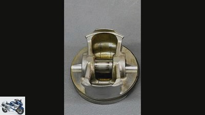
The rear view: The cast piston has relatively thick webs between the piston skirt and the hub.
10/15
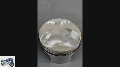
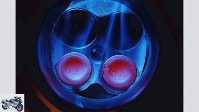
In comparison: the BMW S 1000 RR piston head with CNC-milled valve pockets and a smooth surface on the pinch edges.
11/15
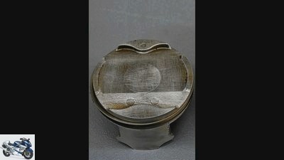
Here is a cast and unmachined piston head from a Japanese large-scale production engine with correspondingly large tolerances in shape and volume.
12/15
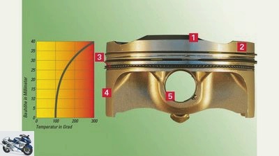
To illustrate: 1) piston crown 2) top land 3) ring zone 4) piston skirt 5) piston hub
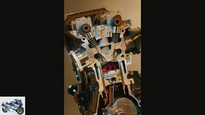
13/15
In the work cycle, the piston is pressed down by the combustion pressure at over 100 bar (red arrows) and reaches a speed of around 110 to 130 km / h at 12,000 rpm, depending on the stroke. The piston is pressed against the pressure side with great force (green arrows) through the connecting rod that is positioned towards the front (white angle). During the upward movement, the connecting rod rests on the opposite cylinder wall.
14/15
The third part of the PS technology series is about pistons, connecting rods and cylinders – and for these three components, maximum acceleration does not always mean maximum fun. For pistons and connecting rods, it is more of a torture rollercoaster ride: at 12,000 rpm, around 100 bar combustion pressure is applied.
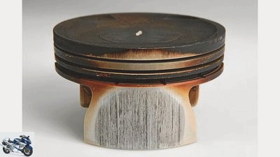
15/15
This is what a piston looks like with scuff marks on the shirt, caused by too much fuel that has washed off the lubricating film. Even if the oil is diluted due to a mixture that is too rich, such traces will appear.
counselor
technology & future
Cylinder piston connecting rod
PS technology series part 3
Cylinders, pistons, connecting rods
Content of
Only when the pistons hit the lid with a combustion pressure of around 100 bar can things really move forward. What puts a fat grin on the face of the sportsman is pure torture for pistons and connecting rods.
Werner Koch
06/18/2013
It is this brief magical moment when the compressed mixture of fuel and air is set on fire by the spark plug that ignites our passion. We remember the first successful attempt to start with our own moped, the rattling and banging when we were “mobilized by someone else” for the first few meters, so to speak, and swept along the streets at lightning speed. What a feeling, just turn the handle on the right and off you go.
Buy complete article
PS-Technik series part 3
Cylinders, pistons, connecting rods
6 pages) as PDF
€ 2.00
Buy now
What we tick off as a matter of course today is pure hell with a detailed analysis of a muscular sports engine. Why? Because the compression pressure alone heats the compressed mixture to around 500 degrees Celsius before the ignition spark generates a flame front that is over 2000 degrees. The combustion chamber, mixture and ignition point must be designed in such a way that the highly explosive mixture does not explode, but burns in a controlled manner. But even in optimal full-load operation, the aluminum alloy of the piston is heated to over 300 degrees, which the piston releases via the rings to the cylinder wall, which is surrounded by the cooling water. In addition, cooled down engine oil is sprayed onto the piston crown from the crankcase.
workshop
PS technology special
Further training for motorcyclists
read more
The detonation
An uncontrolled explosion of the air / gasoline mixture – also known as detonation in the technical jargon of engine builders – would destroy the engine in a few seconds due to the extreme heat and the short but high peak pressure. What happens when the engine “spikes”, i.e. the mixture ignites by itself. This condition occurs when the compression ratio, the ignition point or the fuel quality (octane number) are incorrectly selected. As a result, the edges of the aluminum piston or the center of the piston crown melt. In order to still be able to set the compression as high as possible in series engines – in addition to high performance, high compression also results in low consumption and reduced emissions – so-called knock sensors control the combustion in many engines and regulate the ignition and injection quantity if necessary.
In order to keep the flame paths as short as possible, two spark plugs (double ignition) are often used in large-volume two-cylinder engines, which ensure that the mixture burns completely even in remote areas. If it does not, the toxic hydrocarbon compounds escape unused in the outlet. Mixture residues are preferably “hidden” in the air gap of the top land above the piston rings, which is why this volume should be as small as possible.
More than five tons of peak pressure
Most of the circumferential pinch zones in the cylinder head are also extremely small. This trick ensures that the combustible mixture is concentrated in the middle of the cylinder and is completely burned there. Experienced tuners place the air gap of the pinch edges so close to the piston crown that at maximum revs there can be a very delicate metallic contact between piston and head, which, however, does not play a role in durability in racing. Especially since the gas cushion acts as a damper between head and piston at full load. In racing engines with a stiff crank drive, statically measured pinch edges of 0.20 to 0.30 millimeters can certainly work. Such marginal designs can only be implemented in large-scale production if the combustion chamber and piston are precisely manufactured using precise CNC machining.
With controlled combustion, the flame front initially spreads at a lame 20 to 30 meters per second after ignition, and then increases to a rapid 200 m / s. A working pressure of around 100 bar is generated. Transferred to the area of a piston with a diameter of 80 millimeters (5027 mm²) as in the BMW S 1000 RR, this results in more than five tons of peak pressure that load on the piston, pin and connecting rod. The highest working pressure is reached around 15 degrees after top dead center.
Pistons neither round nor cylindrical
In addition to the extreme gas forces, there are the inertia forces to which the pistons and connecting rods are delivered at 12,000 rpm. After all, it is important to brake the piston from a top speed of around 110 km / h, which it reaches at around half the stroke, to zero in just over a thousandth of a second, or to accelerate it again to this speed. The BMW piston, which weighs 250 grams, achieves a dynamic inertia force of around 6300 Newtons, i.e. a weight equivalent of more than 600 kilograms and thus 2500 times its own weight. A good reason to design pistons as light as possible, especially since the oscillating masses not only destroy energy, but also generate more or less powerful vibrations.
In order to withstand the extreme pressures and temperatures at full throttle, high-performance pistons are nowadays designed as so-called slipper or box pistons, while heavy full-shaft pistons were used in the past. In doing so, the technicians rely on the most stable possible construction made of webs or boxes that support the piston crown towards the piston hub. Even if it looks like this at first glance and makes sense for the layperson, pistons are neither round nor cylindrical. Due to the different high mechanical and thermal loads, the contour of the pistons is correspondingly convex and oval.
The cylinders
The cylinders themselves are usually coated with a wear-resistant silicon-carbide-nickel alloy that is only a few hundredths of a millimeter thick to reduce friction. Today, gray cast iron bushings can only be found in cheap motorcycle engines.
The cylinder bore is made absolutely round and cylindrical by honing. The running clearance between the piston and the cylinder wall is five to eight hundredths of a millimeter in water-cooled engines. The cooling water only flows around the upper third of the cylinder bore, i.e. the area in which critical temperature peaks occur. This reduces the so-called wall heat losses, which draw energy from the combustion process and increase consumption as useless waste heat.
The construction and design of the compression rings are decisive for sealing, especially at low and medium speeds. Formerly made of sensitive gray cast iron, today two extremely narrow steel rings (0.75 mm) with mostly coated surfaces and the lowest possible preload are used. The small contact surface of the razor-sharp rings ensures a high level of tightness so that the combustion pressure does not escape into the crankcase as a so-called blow-by. Despite the immensely high pressures, it is expected that only around one percent of the gases will find their way into the crankcase. The oil control ring, or rather the oil control rings, is located in the lowest groove on the piston, because in modern engines two oil control rings that are only 0.4 millimeters thick are installed there, in the middle of which a wave-shaped band spring is inserted, which transfers the excess oil from the cylinder wall small bores in the piston and thus back into the crankcase.
Friction eats up performance
The short piston skirts ensure low friction with good guidance and thus ensure mechanically quiet engine operation. The narrow piston skirts have to withstand a lot when the piston is pressed against the cylinder wall by the inclined position of the connecting rod with heavy lateral force. This lateral force is around 15 to 25 percent of the working pressure. Which is why not only racing pistons are often coated with a graphite / carbon alloy to reduce friction.
In addition to the working pressure in the cylinder, the ratio of stroke to connecting rod length is also decisive for the lateral force. The shorter the connecting rod, the greater the lateral force, as the connecting rod deflects more from the cylinder axis. Depending on the intended use and objective, the appropriate length results from the ratio of stroke to connecting rod length. If you take the example of our flagship engine from the BMW S 1000 RR (stroke 49.7 mm, connecting rod length 103 mm), the ratio is 0.48. With the Kawasaki Z 1000 engine (stroke 56 mm, connecting rod length 106.2 mm) it is 0.52, while in car engines with around 0.3 the connecting rods are significantly longer in relation to the stroke, i.e. also heavier.
Connecting rods only bring the force to rotate
To reduce the lateral force, the piston pin bore, the so-called hub, is often attached off-center in the direction of rotation of the engine. This reduces the inclination of the connecting rod and thus the side forces on the pressure side during the work cycle. In the case of the Kawasaki Z 1000, this offset is 0.5 millimeters from the central axis. The connecting rod is generally divided into two sections, which, however, flow into one another. On the one hand, there are the rotating masses, which are grouped around the connecting rod foot, and the oscillating masses, which include the shaft and the upper connecting rod eye.
In order to save weight in the oscillating area, the upper connecting rod eye can be tapered trapezoidally. In the eye itself, plain bearing bushes are no longer used in the vast majority of large-scale series engines. In these cases, the bolts and connecting rods run steel on steel. According to the pure theory of engine construction, this friction pairing is one of the worst, but it has also proven itself surprisingly well over long distances, at least in four-cylinder engines with relatively small individual displacements. The best way to save weight on the connecting rod is to use a titanium alloy. Due to the somewhat lower strength of the light material, the dimensions have to be increased slightly, but a weight saving of around 40 percent is guaranteed.
Material alloy and manufacturing process
The shape of the connecting rod can vary depending on the material, geometry and philosophy of the manufacturer. However, the double-T structure of the connecting rod shaft is carried by all forged steel connecting rods, with the exception of the so-called knife connecting rods, which were mainly used in older two-stroke racing engines. In the case of milled titanium connecting rods, on the other hand, an H cross-section increases the flexural rigidity. A shape that has not caught on with forged large-scale parts. The material alloy and the manufacturing process are decisive for the strength of the connecting rod, which is exposed to a permanent alternating tension-compression load. In high-performance engines, the connecting rods are drop-forged from heat-treated steel. The grain of the material is retained, which significantly reduces the risk of breakage.
The connecting rod cover is screwed to the connecting rod foot, which creates the articulated connection to the crankshaft and is therefore lined with two half-shells made from a three-material bearing. Two high-strength expansion screws are used for this. In most cases, these covers are machined together with the connecting rod after forging and guarantee the absolutely correct seating of the bearing shells by means of dowel pins or dowel screws. BMW, on the other hand, relies on so-called “cracked” connecting rods. After machining, the bearing bore is burst open by a forced break, which means that the break points are given an absolutely precisely fitting structure and can therefore do without adapter sleeves. Both connecting rods and pistons are weighed and assigned to a specific weight class by means of markings. This alignment ensures the smoothest possible mass balance and low-vibration engine operation.
Technical basics and tips
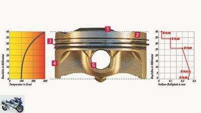
PS
technical basics.
1) The piston crown
It is exposed to the highest temperature (see diagram above left) and transmits the entire combustion pressure. Its shape depends on the angle and size of the valves and the desired pinch edge. It also specifies the so-called compression height (distance from the center of the piston pin to the piston crown).
2) The top land
Here, too, high temperatures and a correspondingly large material expansion occur, which is why the piston diameter is reduced in this area (see diagram above right). The harmless oil carbon deposit is correspondingly strong.
3) The ring zone
There are usually two compression rings and an oil control ring in the screwed-in ring grooves. This area is also still very hot and is correspondingly reduced in diameter, which is why unwanted fresh gases are “hidden” in this free space.
4) The piston skirt
The piston skirt takes the lead in the cylinder and is intended to reduce piston tilting. In direct contact with the cylinder wall, wear and scuff marks can occur here. The piston has its largest diameter around ten millimeters from the lower edge, which is why the piston installation clearance is measured at this point.
5) The piston boss
The piston pin sits in its finely machined bore. It is fixed on the left and right by safety clips.
Tips and Tricks
In the field of pistons / connecting rods, there is nothing to be done with tuning in the homemade way. Only the few, really good tuners and parts suppliers can help here. Certain tolerances can only be omitted when purchasing new parts-
sort, provided you have enough parts to choose from. For piston rings, for example, the parts with the smallest joint clearance are preferred; for pistons and connecting rods, the weight should be identical. Subsequent coating of piston pins and piston skirts with carbon helps to reduce friction and release power.
When the cylinder is re-coated, the tightness in the area of the ring zone can be increased by tapering the cylinder bore conically upwards by around 3/100 millimeters. However, this can only be done in consultation with the respective specialist company.
Addresses:
Great Guardian
Dietmar Franzen / Sport Evolution
Jens Holzhauer
Ten Kate
Sepp Buchner
Hertrampf
Dominik Klein
Related articles
-
Honda NR 750 with oval piston engine
Honda counselor technology & future Honda NR 750 with oval piston engine Motorcycle story Honda NR 750 with oval piston engine In 1991, Honda presented a…
-
BMW Motorrad voluntarily exchanges cylinder heads: S 1000 RR (2020)
BMW counselor technology & future BMW Motorrad voluntarily exchanges cylinder heads: S 1000 RR (2020) BMW S 1000 RR with problem valves BMW exchanges…
-
Aprilia RS660-Tuono 660 recall: engine replacement due to connecting rod
Aprilia 51 pictures Aprilia 1/51 Aprilia launches the new RS660. Aprilia 2/51 The two-cylinder should stir up the market for mid-range athletes. Aprilia…
-
3 cylinder special – three cylinders from the 70s and 80s
fact 17th pictures archive 1/17 Kawasaki 750 H2. archive 2/17 Most drivers who wanted to take on the 750-H2 looked into the tube, or rather into these…
-
Mash 650 Six Hundred: single cylinder with a classic look
News 2022 New motorcycle items for 2022 Mash 14th pictures Mash 1/14 Mash is upgrading its 650 range with another single-cylinder model. Mash 2/14 The…
-
Herald Brute Concept naked bike single cylinder
Herald Motorcycles counselor technology & future Herald Brute Concept naked bike single cylinder Herald Brute Concept Minimalist British single The small…
-
Kawasaki Z1 cylinder heads new parts
Jahn counselor traffic & business Kawasaki Z1 cylinder heads new parts Kawasaki reissues Z1 cylinder heads More classic new parts are to follow Kawasaki…
-
Drawing: archive counselor technology & future Technology guide: lubrication Technology guide: lubrication Knowledge: Nothing works without oil From the…
-
motorcycles Enduro Technology Honda CRF 450 R Technology Honda CRF 450 R For the sake of simplicity Why complicated when it can be made easy? This is…
-
New 500cc two-stroke Bimota engine
counselor technology & future New 500cc two-stroke Bimota engine New 500cc two-stroke Bimota engine Easy sense While the Japanese are turning their back…